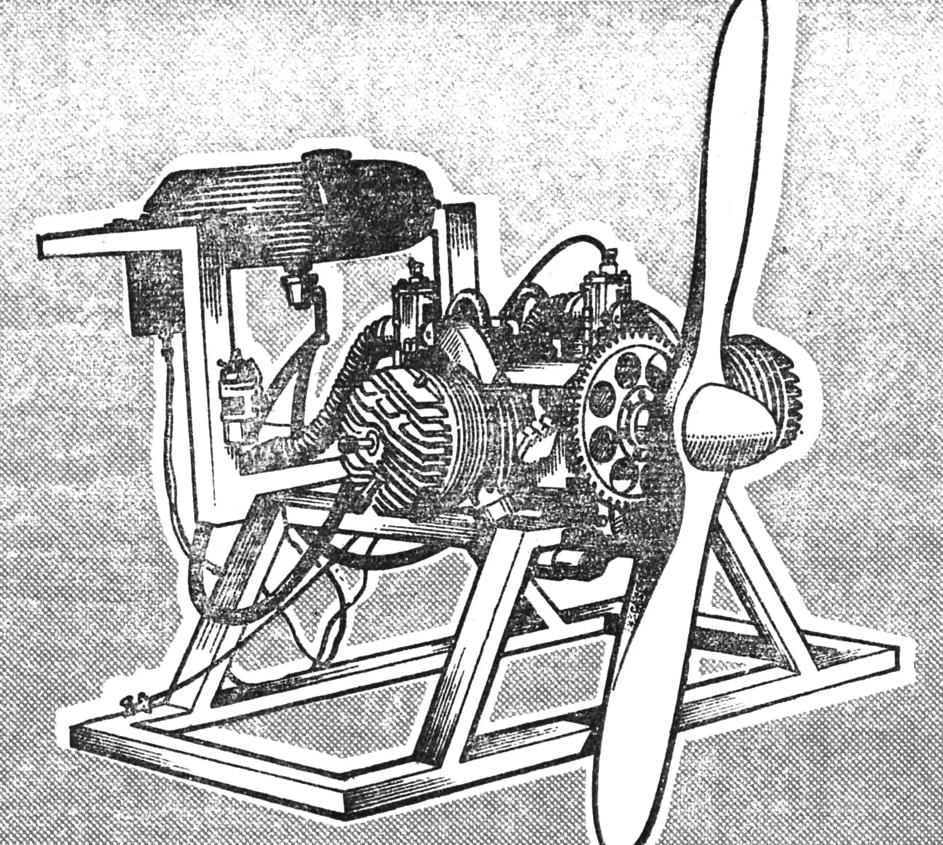
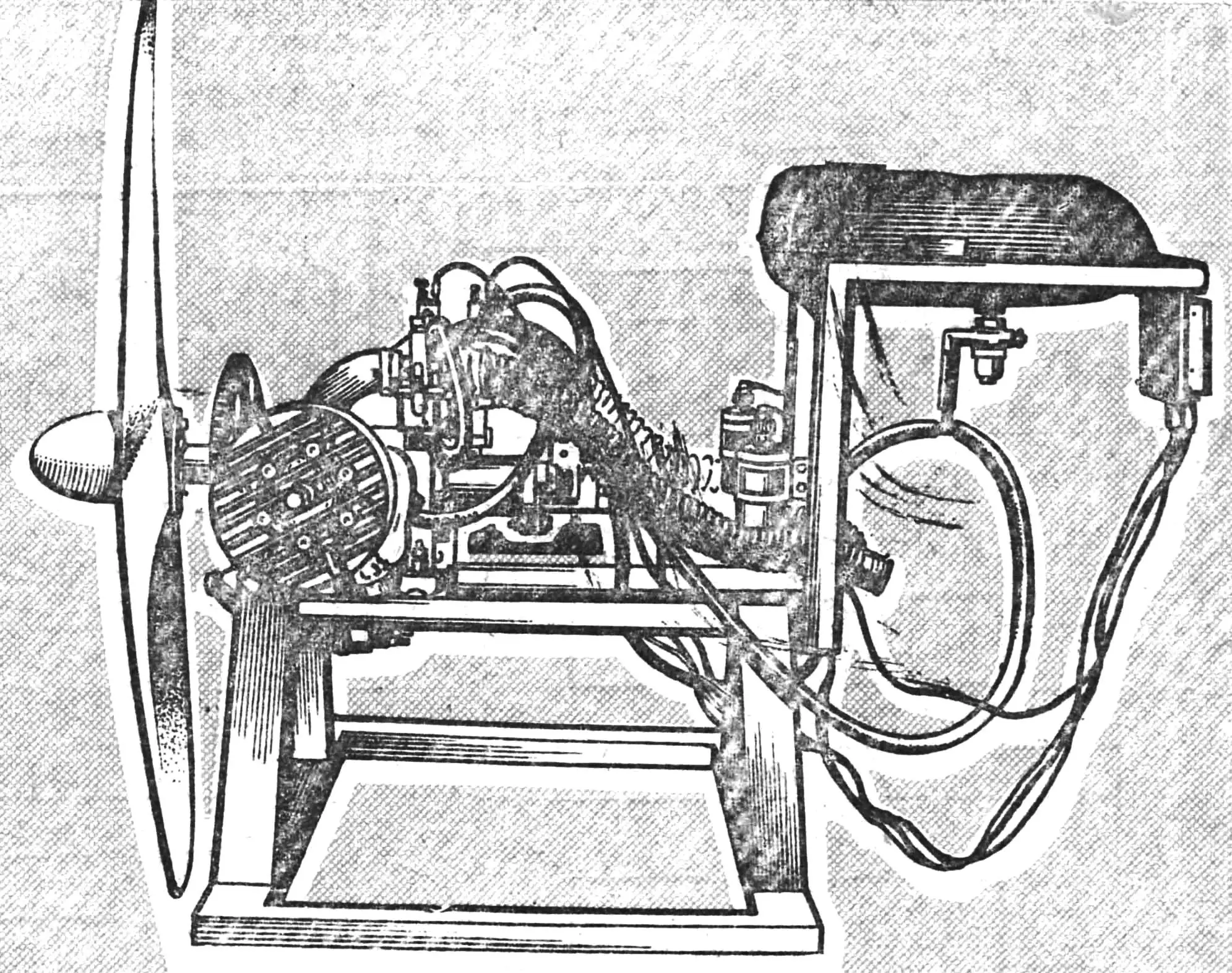
This two-cylinder engine, designated DD-700/40, was designed and built by Georgy Dorfman, head of the public design bureau “Aerosam”. The motor turned out to be exceptionally successful: reliable, relatively simple, and quite lightweight.
The motor was exhibited at the IV All-Union Review-Competition SLA-87 and was approved by the technical commission of the rally.
To date, several examples of such engines have already been built, and all of them have shown practically identical characteristics and consistently high reliability. Currently, “Aerosam” is designing a power plant with a dismountable crankshaft and a valve intake system. In addition, an opposed four-cylinder motor with a power of about a hundred horsepower is being built.
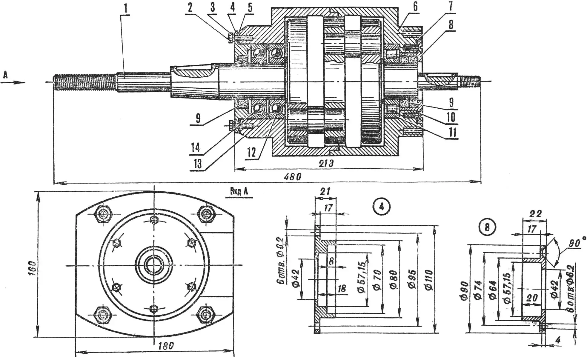
1 — crankshaft, 2 — bolt M6, 3 — washer, 4 — front cover (steel 30KhGSA), 5 — front gasket (install on bakelite varnish), 6 — crankcase (D16T), 7 — rear gasket (install on bakelite varnish), 8 — rear cover (D16T), 9 — seal 40X57X10 mm (from VAZ car engine), 10 — screw M6, 11 — bearing No. 2208, 12 — bearing No. 36208, 13 — ring 80X70X2 (steel 20), 14 — bearing No. 208
When designing the DD-700/40 engine, we tried to maximize the simplification of its unit design and achieve high reliability in operation. To fulfill the first condition, we relied on the use of parts from serial motors, and for homemade ones, we provided for the use of advanced technological techniques.
As follows from the motor’s name, its displacement is 700 cm³, power — 40 hp. By the way, the latter characteristic was obtained not only through calculations but also during bench tests, with the crankshaft rotation speed being 5100… 5600 rpm. The engine mass without the propeller, electric starter, gear ring, and electronic ignition is only 36 kg — that is, less than a kilogram per horsepower.
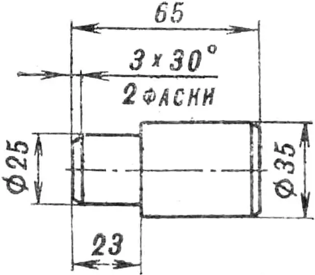
CRANKSHAFT. The crankshaft cheeks are made of steel grade 30KhGSA. First, three completely identical blanks are machined on a lathe — their diameter is 140 mm, thickness — 23.5 mm. Then the obtained “pancakes” are hardened to HRC 33… 38, after which they are ground to a thickness of 23 mm.
The holes in the cheeks Ø 25H7 and Ø 35H7 are bored on a jig boring machine. In this case, one should achieve minimal limit deviations in the tolerance field towards increasing the diameter.
The crankshaft journals are made of steel 40KhNVA. Blanks for them are turned with an allowance of 0.5… 0.7 mm in diameter, the cylindrical section Ø 40 mm and the cone — with an allowance of 1.5 mm. Keyways are milled in the blanks and locking holes are drilled, after which these parts are heat-treated to HRC 48… 54. Note that with lower journal hardness, seals will quickly “eat” the shaft. Hardened blanks are processed on a shot blasting machine, then cylindrical sections with diameters of 35I8, 48, 18, and 12 mm are ground. The thread must be cut on a thread grinding machine.
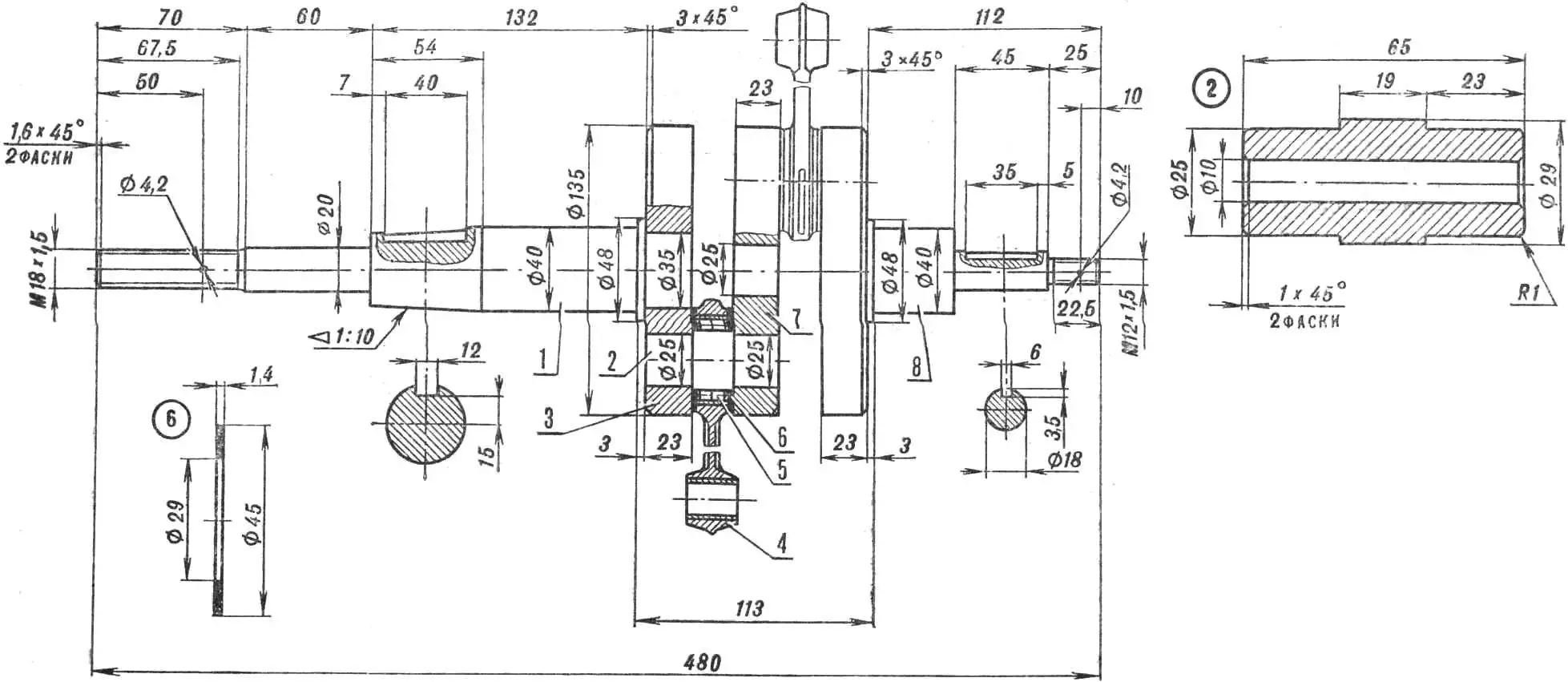
1 — front journal (steel 40KhNVA), 2 — crank pin (steel ShKh-15),3 — outer crankshaft cheek (2 pcs. steel 30KhGSA),4 — connecting rod (finished product type IZh-P), 5 — bearing No. 822906, 6 — side bearing washer, 7 — inner crankshaft cheek (steel 30KhGSA), 8 — rear journal (steel 40KhNVA).
The lower connecting rod pins are made of steel ShKh15. Blanks should be heat-treated to HRC 62… 65.
Crankshaft assembly is a very responsible operation. It begins with the lower connecting rod pins being deeply cooled in liquid nitrogen and pressed into the middle crankshaft cheek using a screw or hydraulic press.
Next, a connecting rod bearing and connecting rod with bon washers are assembled on one of the pins. To prevent the rollers from scattering, they are fixed in any way. The cheek with the connecting rod is also cooled in liquid nitrogen, and a plug is inserted into the middle hole of the cheek; the groove in it should be directed towards the connecting rod. Then the outer cheek is put on the plug — in this case, it will serve as a guide along which the outer cheek will slide during pressing. To avoid crushing the cheeks and bending the connecting rod pins, ground spacers 19 mm thick are inserted between the cheeks during pressing.
The same operation is repeated for the second outer crankshaft cheek. First, the plug is knocked out and inserted into the middle cheek from the other side, after which follows deep cooling of two already assembled cheeks with connecting rods and pressing of the second outer cheek.
The assembled crankshaft is ground in the centers of a grinding machine. Then the cheeks are turned on a lathe to Ø 135 mm. The shaft runout at the bearing installation locations should not exceed 0.02 mm.
CRANKCASE COVERS. The front cover is turned from steel grade 30KhGSA, heat-treated to HRC 33… 38. Coating — cadmium plating. The rear cover is made of duralumin D16T. Seals are from the crankshaft of a VAZ car engine.
CRANKCASE. For the crankcase, a duralumin (D16T) round blank Ø 210 mm will be required. Crankcase half blanks are faced and bored from the inside in one setup. Drilling of threaded holes and boring of holes Ø 12H7 is performed on a jig boring machine. As a last resort, these holes can be machined on a drilling machine with subsequent reaming.
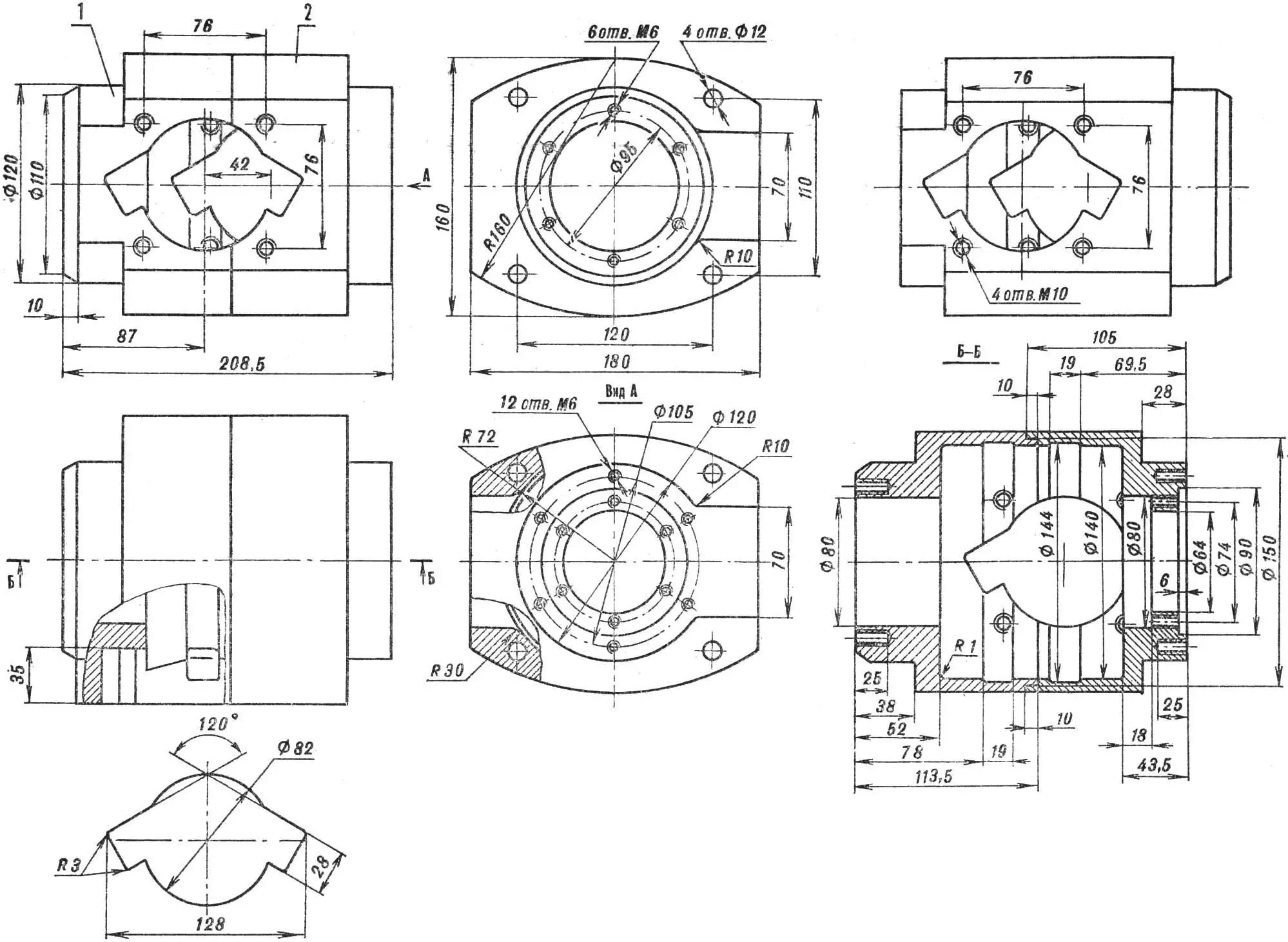
1 — crankcase nose (D16T), 2 — crankcase tail section (D16T). Bottom left — window configuration.
Finish milling of crankcase halves can be performed everywhere except the groove with a size of 180 mm — there a 2 mm allowance is left. After milling, the crankcase halves are joined using tie studs, and then the specified groove is finally machined. Next, on a milling machine using a rotary table, holes for cylinders and their mounting studs are machined. Flats with a radius of 30 mm on the edges of bores Ø 142 mm are made with a file so that the connecting rods do not catch on the crankcase. And the last operation — anodic oxidation.
SEVERAL RECOMMENDATIONS. When manufacturing parts, one should achieve surface cleanliness, maximally possible for the machine equipment used. On the holes of the flywheel cheeks, chamfers of at least 0.5X45° must be removed. Pressing should be performed in the shortest time, so we advise to practice beforehand and carefully rehearse the sequence of operations taking into account their features. Pressing with heating is not suitable in this case — it causes irreversible changes in the strength and surface hardness of crankshaft parts.
READY UNITS AND PARTS. The DD-700/40 engine uses cylinders and cylinder heads IZh-P3, carburetors type K-62I, connecting rods IZh-P with connecting rod bearings No. 822906 and side washers, upper connecting rod pins with retainers, bearings No. 208, 36208 (or 46208), 2208, as well as pistons IZh-P.
ADDITIONAL EQUIPMENT. Our engine is equipped with three sets of ignition devices. These are battery electronic, battery contact, and reserve magneto type M27B, whose breaker is used for battery ignition. An M90 magneto can also be installed on the engine, providing two sparks simultaneously.
It should be noted that an attempt to convert a conventional magneto into a dual-spark one did not lead to success — the spark turned out to be “weak”, and such a magneto only reduced the reliability of engine operation and, accordingly, increased the probability of its failure.
To improve engine cooling, we recommend milling seven upper cooling fins of the cylinders to Ø 180 mm. Cylinder heads are turned on a lathe.
The engine is equipped with two fuel pumps from the “Moskva-30” outboard boat motor. Pump drive fittings can be cut into cylinder bypass channels or into the crankcase.
For its starting, an electric starter ST-366 from a “Zaporozhets” car engine is intended, connected to the crankshaft through a gear wheel attached to the rear flange of the air propeller with six bolts with M6 thread. The gear wheel has the following parameters: number of teeth — 91, module — 2.5, center distance — 125.0 mm. Keep in mind that starting the motor by hand jerking the propeller is very dangerous, as this requires applying significant force.
Motor mounting to the frame is performed with two sets of pairwise connected L-shaped brackets mounted on extended ends of the lower tie studs.
It is advisable to install mufflers on the engine. Power losses will be insignificant, while driving comfort will significantly increase and fire hazard will decrease.
“M-K” 6’88, G. DORFMAN, head of public design bureau “Aerosam”
Recommend to read
 WALL FOR EVERY TASTE
For anybody not a secret: getting a new apartment, often have to finish something before the builders. All these little "improvements" sometimes outgrow almost overhaul. Of course, you... THE TECHNOLOGY IS OLD -VELOCITY NEW
Vyklevyvanija corps on the disc or in the inverse matrix has become today an accepted technology of making high-speed RC boat. The shell in this are light, durable and usually require...
