 In many CUT and suit (clubs and centres for young technicians) a section of the kart. Little machine not only helps children to learn the overall concept of the car and learn the basics of his driving, but many of them, it’s blazing a trail in the big Motorsport and reveals their ability in technical work.
The training program of the event provides the initial phase acquisition by children of skills of manipulation of clutch pedals, throttle, brake, gear shift grip. But the final step when engine is prohibited by the manual, as it can cause damage to the gear. When you opened the motor to do it just unsafe: card driven, and the learner is, in fact, for the first time sat down behind the wheel, still does not know how to manage it.
Even if syt has a real car simulator, then after school the boys the desired effect on the acquisition of skills on the map do not reach. It is very specific machine cards and its management bodies. Even the driver’s Seating position on it is different.
In some sections of the original exercises by manipulating pedals map is carried out by lifting the rear wheel installing the rear part of the frame on the stand. But it is also unsafe — vibration card can “pull” with stand. For motor and gear, this method is also not harmless — the motor is running without load at significant speed “racing”, smoothly to switch between the programs is simply impossible, and then again, quite likely damage to the car.
We have found a way out of this situation by constructing and crafting a training stand that meets the requirements of the curriculum and safety.

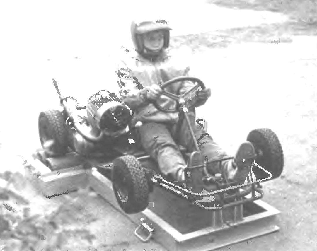
General view of the stand:
1 — roller bearings (St3, 4 pieces); 2 — holders of roller supports (40×40 area, 4 PCs.); 3 — clips (4 PCs); 4 side bracket (St3, sheet s5); 5 — frame (channel No. 10); 6 front brackets (St3, sheet s5); 7 handle (2 PCs); 8 — wheel (2 pieces); 9 — edge (St3, the sheet s5, 4 PCs.)

Video:
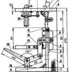
1 — Circlip (wire Ø2. 5); 2 — small labyrinth bushing, 3 — a big labyrinth bushing; 4 — thrust ring (St3, sheet s2); 5 — the bearing housing (steel 45, the range 122); 6 — casing roller (45 steel); 7 — axle (steel 45, the range Ø34); 8 — bearing 80406 (2); 9 — bearing housing studs (steel 45, the range 122); 10 — rubber pad (s3); 11 — cover (St3, sheet s6); 12 — screw М6х12 (4 PCs)
The basis of the stand — frame, welded from channel No. 10 (but it can be done from channel No. 8). It is composed of two rectangles, stacked in the shape of the letter T.
Top, sides, and rear of the frame, has 4 roller bearings (2 right and 2 left). Each of them is a bar with tapered bores in the roller axis, with the welded bracket of the area of 40×40 mm.
To increase the rigidity between the flanges of channels under the axes of the rollers welded plate-fin.
On top of the frame of the stand mounted three brackets: two in the front under the cross member of the frame of the map and one side under the spar. The first two hold the car in place, and the latter does not allow it to shift from the vibration in the lateral direction. Tube frame map thus drawn toward the brackets with the straps attached to the bolts.
The most difficult to execute host stand clip, besides four of them — two for each drive the rear wheel.

General view of the map on the stand

Blower motor:
1 — motor; 2 — shell casing (sheet s2); 3 — five-blade impeller (from the car “Lada”); 4 — holder of the motor

The power supply circuit of the blower motor:
1 – winding of the generator; 2 – rectifier (diode Д231А) 3 – motor М367
In the cylindrical hollow body of the roller from opposite sides are inserted and seamed the two housings with bearings 80406. Bearings mounted on an axle, which with its conical part is fixed in the support.
On the one hand the roller is covered with a lid with rubber gasket, with the other labyrinth sealing bushings.
Inside the bearings and the clearances of the bushings jams the grease. The assembled roller should spin freely. The effort to bring it into rotation should not be more than 3.2 kgf/cm.
Before assembling the stand card is also modified. First, the engine mounted fan with an electric motor М367 DC voltage of 6 V and power 5 W — wiper motorized С3Д. The generator is on the map — AC. Therefore, the motor power supply is effected from there via odnowiony rectifier Д231А. The five-blade impeller of the fan from the car “Lada”. She closed ring guard.
The fan Assembly is attached with a bracket to the frame map in the location where you installed the engine.
The fuel in the carburetor is fed by gravity from the 1.5-litre metal tank mounted behind the seat back.
Poster maps set the extinguisher from the production of the motorcycle “Minsk”, since these machines are the same engine size — 125 cm3.
Before each exercise stand on the platform should be installed so that the wind was directed at the person of the student and carried the exhaust gas from the muffler.

Stand Assembly
To move the stand back at the end of the frame are mounted two wheels and the sides of the front part of the frame two handles. For them, the stand raised to the vertical position and transported to the desired location.
On rotating rollers of the stand maps is moving like on the way clearly includes all transmission, smoothly increase the engine speed not “sticking” brakes even with a heavy pedal.
Stand simulator made in “Kart racing” CUT Syzran turbine-building factory together with the revision map is designed as a rationalization proposal. Active participation in the creation of the stand taken by members of section A. Baev and A. Kuzmin.
Years of operation of the stand-simulator showed its safety, efficiency, teaching kids basic skills of driving card.
V. STANTIN, teacher syut STZ, Syzran, Kuibyshev obl.


