 How to be autoconstruction mug? What it should build cars? How to organize classes? These and many other questions were raised in the recent publications of M. Larkin, and L. I. F. Rychkova “Project — model — car” and “car Designer — car designer!” (“M-K” № 1, 1979). More of our readers interested in the technical side of things — the device is modular inputs to directly affect. Today we offer the latest development autoconstructor laboratory Cut of the Siberian branch of the USSR Academy of Sciences — the micro-car, only “Protein”.
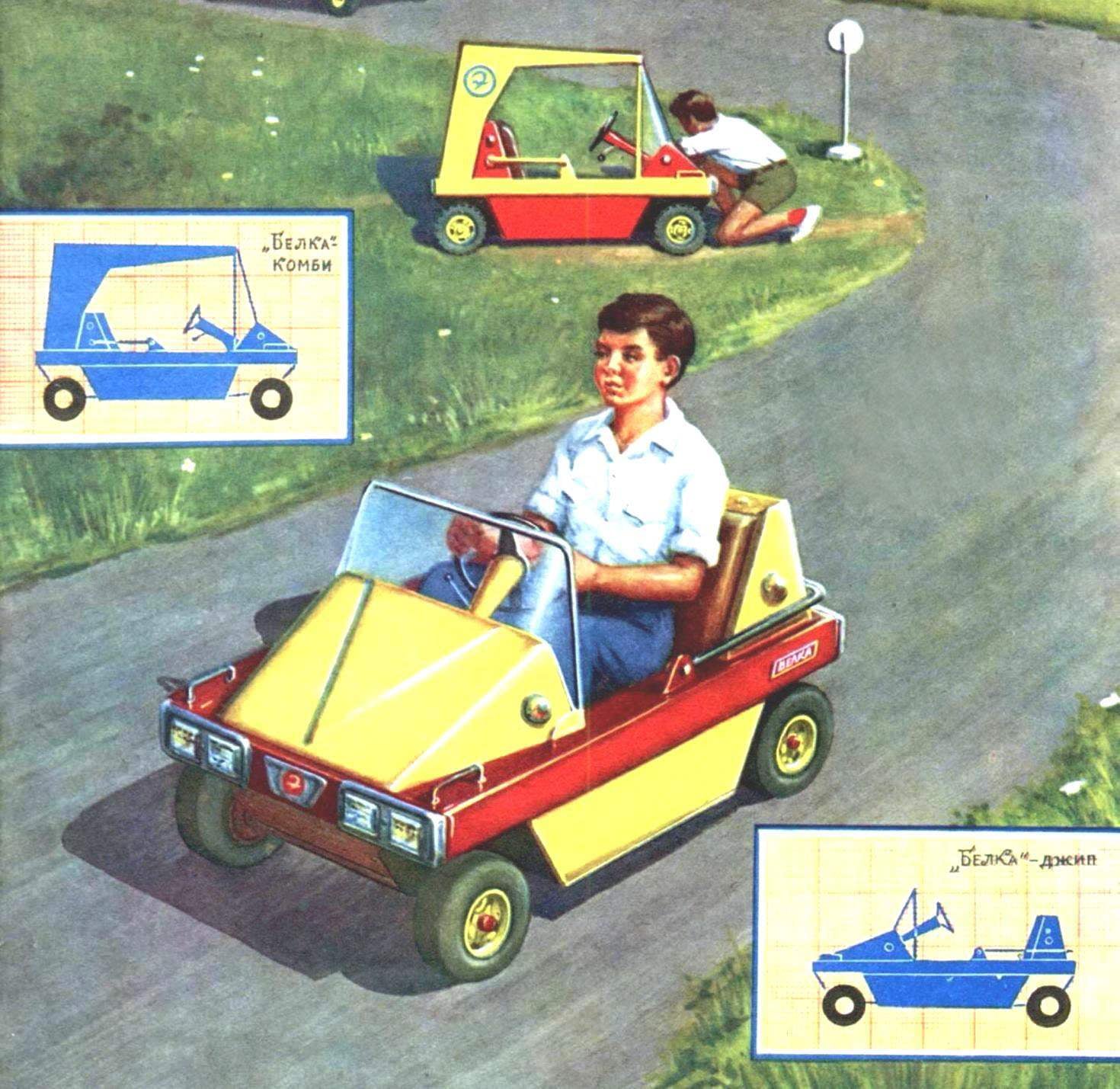
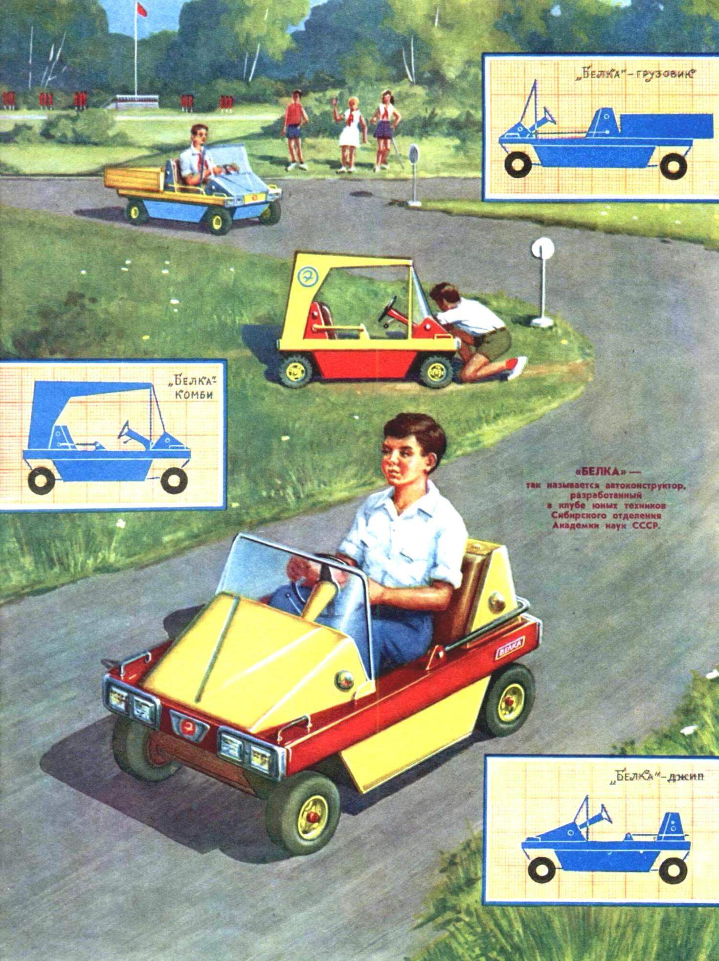
This small, graceful pleasure-sport “jeep” in just half an hour can radically change the entire look. Should rearrange two or three element design and buggy. But if there is a desire to stop “the Squirrel” in a touring car, it is enough to establish a removable canopy fairing. Easily turns it and light truck. If necessary, the car can be easily disassembled and formed into a private truck body as in a box.
Despite the relatively small size (“Protein” freely placed even on a Desk!), it’s not a toy but a real car. Speed about 40 km/h and the fuel in the tank is enough for 100 km.
How did the idea of a modular car? First of all we were not happy about the timing of the design and construction of the “traditional” machines — our boys had time to grow up, finish school and leave the club and not the North never behind the wheel.
Not suitable for us, and schemes of the frame and low-tech in terms of the circle of the profiled panels. Such designs, apart from the fact that their implementation requires too much time and effort that is absolutely immutable — the other car make on the basis of the old very difficult. To build a new car without the use of elements of the old expensive.
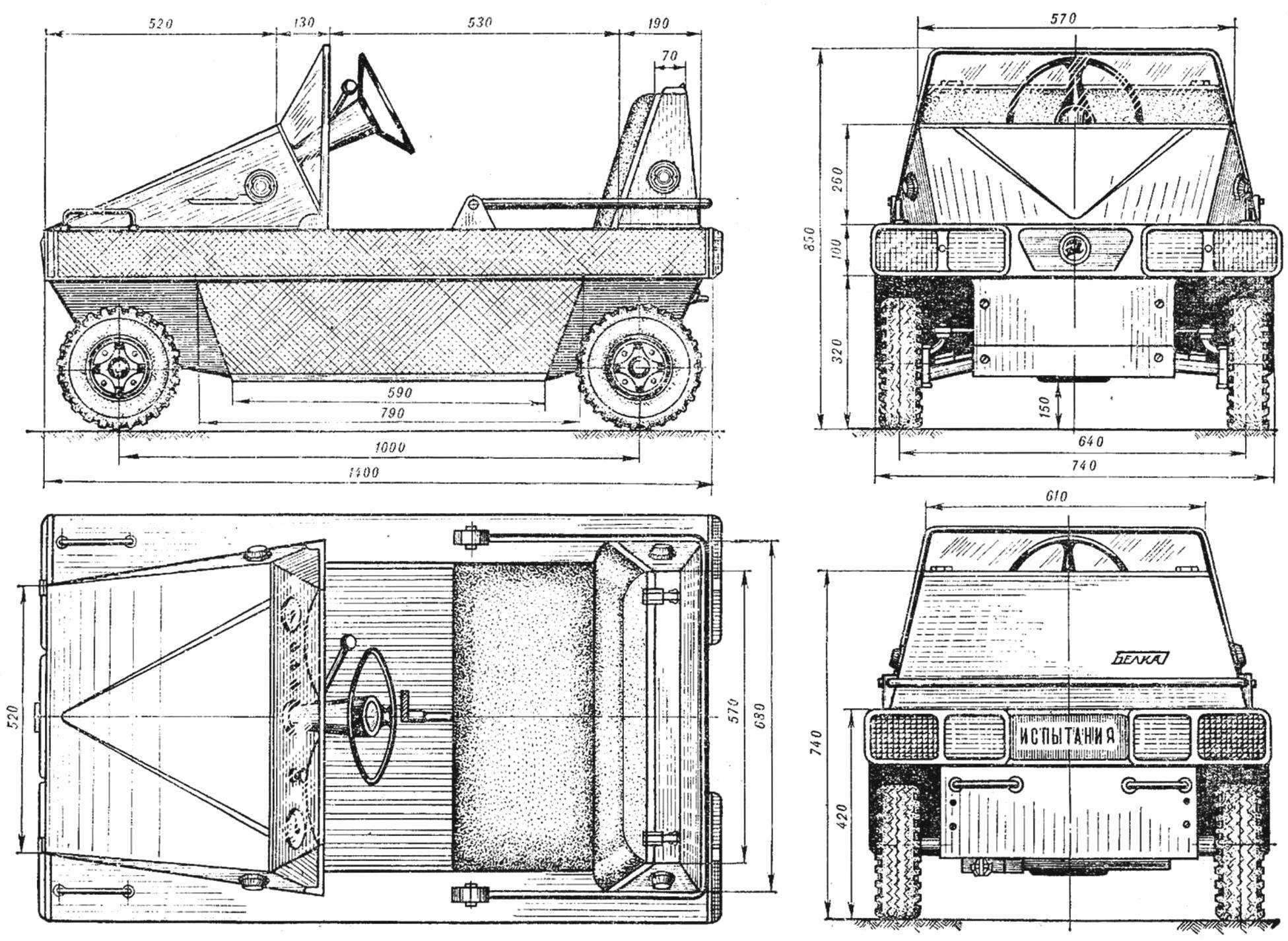
Fig. 1. “Protein” is a modular micro — car, only.
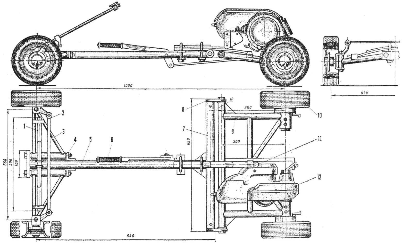
Fig. 2. Chassis inputs to directly affect:
1 — a transverse leaf spring, 2 — lateral pull, 3 — pendulum front suspension, 4 — lug front mount, with 5 spinal frame, 6 — lever start engine, 7 — transverse beam of the frame, 8 — eyelet fastening pendulum rear suspension, 9 — pendulum rear suspension, 10 — rear wheel 11 — longitudinal leaf springs, 12 — the engine of the VP-150.
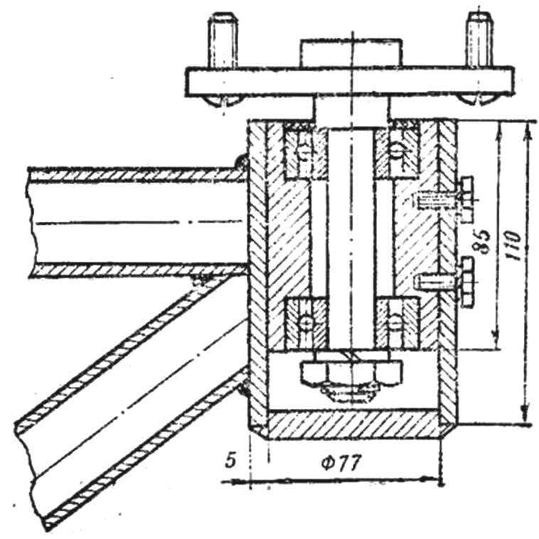
Fig. 3. Hub right rear (free rolling) wheel.
And last what inspired you to undertake the development of transformable little micro-car, is the problem of storage. The number of our developments slowly but steadily increased; several cars we kept in the lab, the rest in the garage. The interest was gone, because the boys wanted to try out for the construction of his car, and gradually the work of several generations of students turned into scrap metal.
All this has forced us to address fundamentally new idea is to design a multi-purpose block (modular) car.
There was, however, and objections: some people thought that the design of such a machine will put a young designer in a rigid framework preventing the flight of imagination. But the majority of people were inclined to believe that this will not happen. On the contrary, limitations in the design will give an opportunity to young avtostroiteley to exercise maximum ingenuity in the elaboration of its own version on the basis of a standard set of elements.
Let us now open the box-body and consider what is the basis of autoconstructor.
Body Proteins-the truck is a box, assembled of six-millimeter plywood and edged dural area. Lie on top of the part of the driver’s seat — back and seat. They are simple — base (plywood 6 mm thick) glued to it with foam covered with artificial leather in red. Overall dimensions seat 570X300 mm.
Under details seat is a steel sheet 720X510 mm, 2 mm thick, covered on one side corrugated rubber is the bottom of the car. Twelve holes of Ø 4 mm at the edge of the sheet is designed for attachment of the floor to the body.
Removing the bottom, you will discover underneath the six side panels, which are the basis of the car body, because almost all the other elements of the body are attached to them.
In the center of the box between the side panels of a space to the four wheels of 3.50—5 model V-25 A. they invested eight wheels and two hub bearings, and axles Assembly with swivel axle and longitudinal rods.
More below are two rocking front axle, welded gas pipes with external Ø 20 mm. Here is the sub frame that serves as both the basis of the rear axle and its suspension. It is welded from gas pipe Ø 30 mm.
In the same box-body stowed and spinal frame of the car square section 40X40 mm with welded thereto a lug for fixing the rocking front and rear axles. Under the frame are two leaf springs (front — rear and lateral — longitudinal), and four of the ladder with the loser” us for attachment of the suspension to the frame. Bands of springs you can pick up from the car “Moskvich” of any brand.
The set designer also includes steering wheel steering column with mounting brackets and collars and cross rod hinges. In a separate package — pedal throttle control of the carburettor, clutch and brakes. To the bottom of the stacked body panel cowl, windscreen, back support seat back (aka — the hood of the tank), front and rear fenders, instrument panel and two steel corner profile 20X20 mm length 720 mm. In a special compartment are lights and sidelights, Parking lights, cables, speedometer, toggle switches, a set of elements of the electric system and a package of fasteners — bolts, screws, washers and nuts. Not forgotten, and end wrenches, screwdrivers.
The engine of the VP-150 is Packed along with the gas tank hose fuel line and kick in a separate box.
Kit car there. Let us now try to make one of the variants of autoconstructor, particularly little micro-car “Protein”-“jeep”.
To begin Assembly of the best from the chassis. For this purpose, the mounting area should be placed in a spinal frame with two M10 bolts to pivotally connect the sub frame and rocking of the front axle. The ends of the front transverse springs enter in the support bracket of the rocking of the front axle and the center of its fasten two ladders to the frame.
In the left sub-frame bushing is inserted into the motor shaft, and he pristykovyvayas stopanim to the frame with two bolts. Axle free rolling wheels with bearings and a holder inserted into the right bushing sub-frame. You can then mount the rear longitudinal leaf spring, one end of which should be in the support bracket under engine suspension frame and the other fixed with two ladders on the cap frame.
We now proceed to the installation of the rear wheels. The first step is to collect three nuts and bolts tyre with the camera and both the disc and the pump wheel. Wheels must be mounted on the studs of the hubs of the rear axles equipped in brake pads and discs. Rear axle, thus is completely assembled.
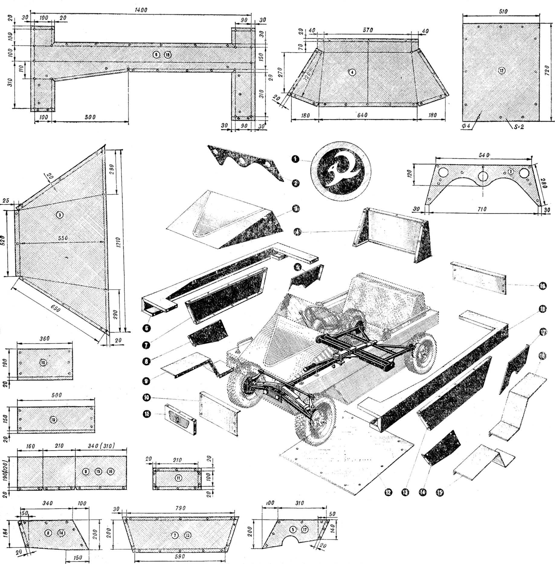
Fig. 4. The main body panel and scanner:
1 — logo 2 — instrument cluster 3 — hood 4 — support backrest, 5, 17 — side rear wing, 6, 18 — underbody, 7, 13 — side panels, 8, 14 — side front wing, 9, 15, 16 — front and rear fenders (dimensions in brackets are for the rear fenders), 10 panel, 11 panel, 12 — bottom, 19 — rear panel.
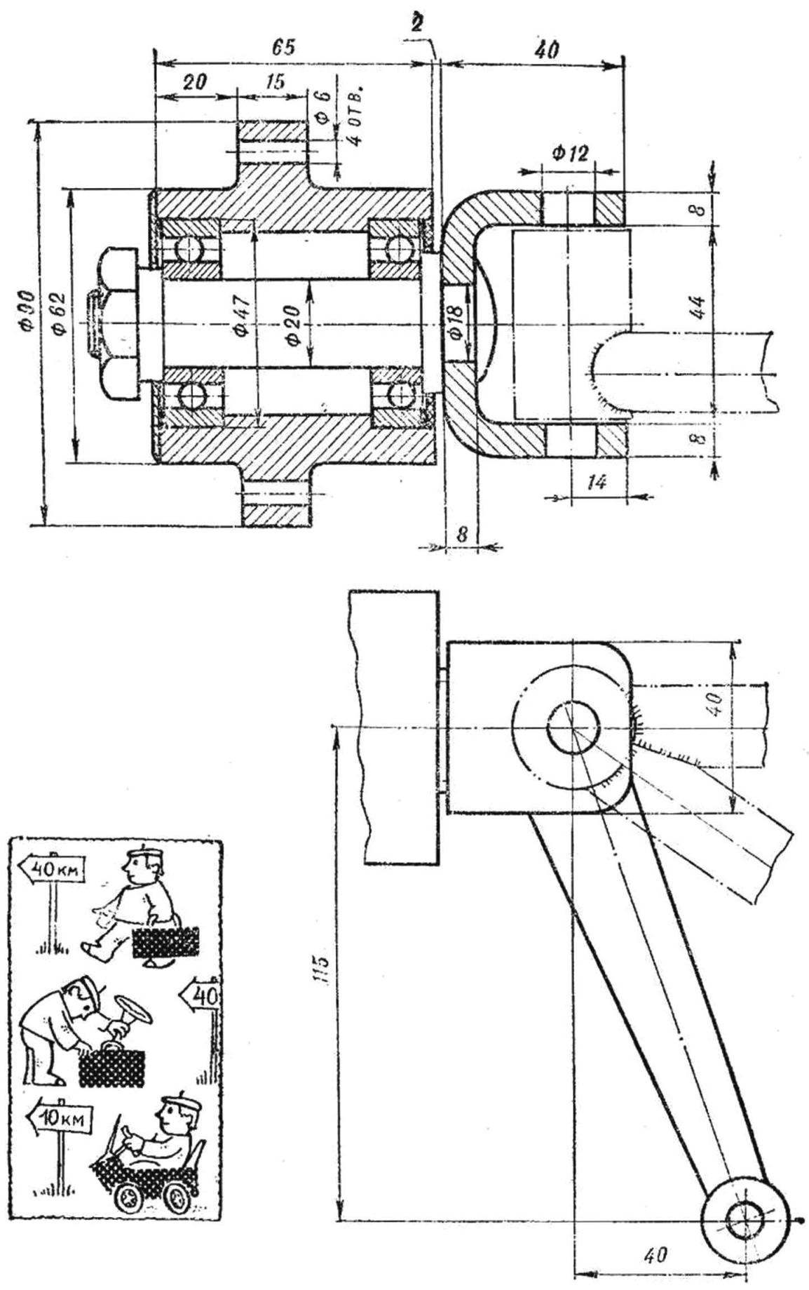
Fig. 5. The front wheel hub with the axle and the axle.
The next stage is Assembly of the front axle. First, fists pumping units are installed two rotary axle with the axes of the front wheels, fixed pins And splintwood. On the half-worn wheel hub with pressed in their bearings. Assembly of the front wheels by kitsch does not differ from the corresponding operations from the rear.
It remains to put in place a steering column and tie bar, and work on the chassis is finished.
Now it is the turn of the body. To begin with, take a pair of base panels of the body and seal them chetyrehkilometrovoy bolts. Next, mount the side panels, fenders with the obligatory insert of sound-absorbing elements. In the front and rear parts of the body formed by the Assembly of apertures mounted two push-in area and fasten them with four bolts. The flanged wings preporacuvam the bottom.
Next, fixed the hood (don’t forget the gaskets!), windshield, instrument panel (screw-tapping), headlamps and taillamps. And finally, the finished casing is mounted the gas tank and on the dashboard — speedometer, toggle switches and the ignition switch. The body is almost assembled, it remains to put in place the pedals and control levers and to mount wiring.
Now a body can be joined with the chassis, install the control cables and the gas lines. The car “the Squirrel”-the jeep assembled. You can hit the road.
M. LARKIN, head of laboratory experimental simulation and design Kuta USSR Academy of Sciences,
Recommend to read
 RISE – CO2
Models with a miniature carbon-dioxide engines attract the attention of a growing number of adherents of the small aircraft. This is understandable: like the plant is extremely easy to...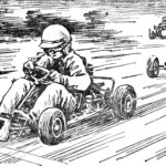 “Pioneer” – karts for beginners
The Pioneer class kart is the smallest of the sports racing cars. The working volume of its engine is only 50 cm 3 . Such karts are built for races in which children aged 9 to 16 years...
