 Machinery and apparatus air cushion (profit centers and WUAs), every year more and more attracted the attention of designers all over the world. This is not surprising. The use of the inherent principle, especially for all-terrain vehicles, allows us to obtain unprecedented off-road capability and speed. They can freely and equally easy to move on the highways and country roads, marshy bog, on the water surface and a plowed field.
The last time the WUAs are becoming popular with designers and Amateurs. After all, the Rover hovercraft in much easier a variety of wheeled, tracked, screw and other machinery. There are no complex drivetrain from the engine to the propeller or such elements of these propulsion, such as wheels, caterpillars.
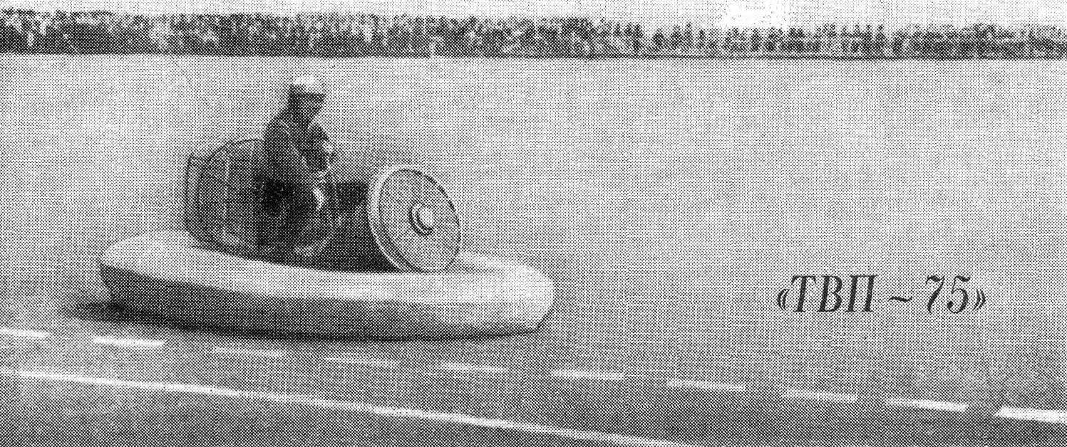
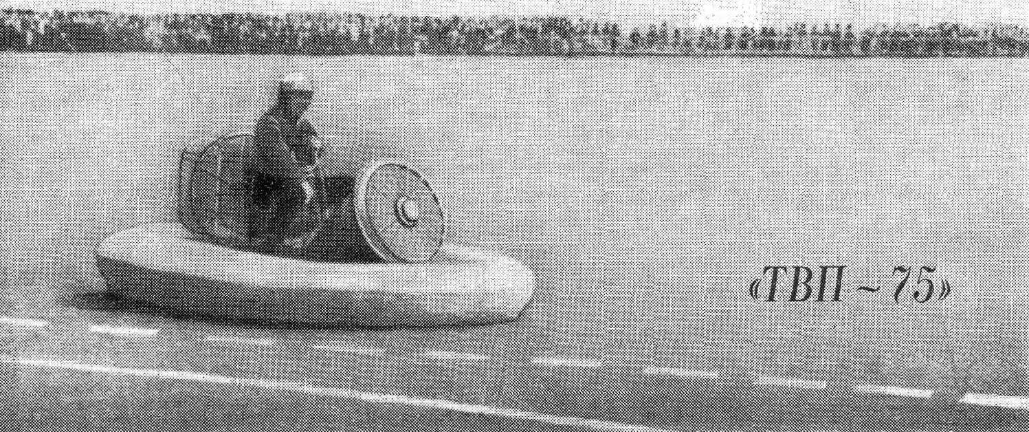
Single profit center designed and tested in the Leningrad Palace of pioneers named after A. A. Zhdanov; in its creation actively involved the children working in the engineering laboratory of the Palace. The first model cars were involved in one of the parade of pioneers in Palace square in Leningrad (see photo). The design presented at the all-Union correspondence exhibition “Create, invent, try” (see # 3, 1975), and we place her today at our booth “TVP-75”.
THE CHOICE OF THE SCHEME AVP
On a small WUAs have spread mainly two of the most simple to execute the scheme of formation of the air cushion: the dome of the figure 1 (a and b) and jet (b and d).
Lifting height H, which determines largely the main parameters of the machine, its maneuverability on rough roads and allowable translational velocity depends on the weight of the vehicle and the overpressure of the air drawn by the fan under the car. In the dome circuit this height (up to a rigid part of the housing) can be increased by installing an elastic “skirt” (see Fig. 1B).
In the nozzle circuit, the a “skirt” performs the air from the circular slit of his “accumulate” at the bottom, pressing on him, whereby the lifting device compared to a conventional dome circuit is increased in 1,3—1,5 times. Jet scheme with one (see Fig. 1) or two circuits (g) and has much more strength in comparison with a domed scheme. That’s why to ensure good driving characteristics of the intended machine on air pillow members of the engineering laboratories of our Palace of pioneers was adopted simple designs one-loop diagram with a single fan (Fig. 2).
CALCULATION APPARATUS
Fan of AVP must continuously feeding air under its bottom, then due to excessive pressure machine is lifted and between its bottom and the supporting surface a gap. The air begins to run through it at a speed of
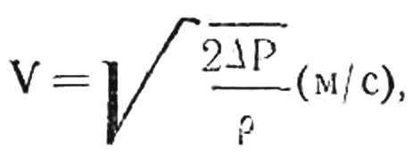
where Δ P is the pressure in the pillow in kg/m2,
is the air density at the ground equal to 0.125 kg·cm2/m
(the formula gives an error of up to 5% for V ≤ 100 m/s).
In case of equal volume coming from the fan air in and out from underneath the machine hangs at a height H = KQ/ПV(m) (for dome scheme).
Here Q is air flow rate in m3/s P — perimeter of the bottom in m V — velocity of air in m/s, K — coefficient equal to 1,25—1,6 (takes into account the increase in the height of the vehicle by narrowing the streams flowing from the slit air flow). Dimensions of the machine are determined on the basis of the required area of the bottom’s roughly when a given weight of the machine:
S = G/P (m2).
where G is the running weight of the vehicle in kg, P is the air pressure in the cushion in kg/m2. The latter will always be less than the pressure developed by the fan.
THE CHOICE OF ENGINES
According to the chosen configuration of the machine it is installed two internal combustion engine: the fan drive and of the sustainer installation. Engines used air cooling.
To drive fan single WUA sufficient engine power 8-14 HP It can be a single-cylinder motorcycle engines with a displacement of 175-350 cm3. The engine is installed in the air flow provided by a fan.
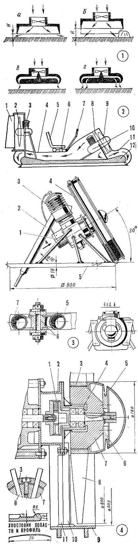
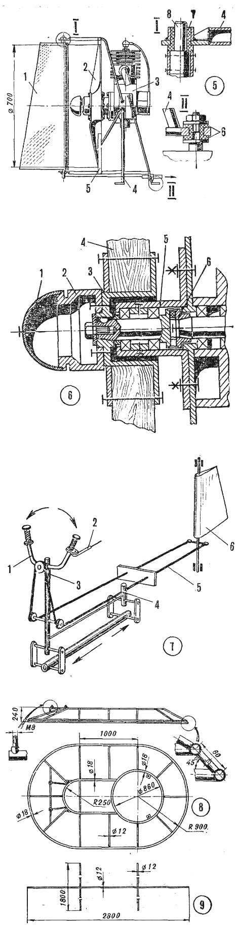
Fig. 1. Scheme of formation of the air cushion:
a, b — dome; C, d — jet.
Fig. 2. General layout drawing of the machine:
1 — rudder, 2 — propeller, 3 — main engine, 4 machine frame, 5 — the driver’s seat, 6 — couch rollers, 7 — control handle, 8 — directing vanes of the fan 9 — fan, 10 — motor, 11 — nozzle, 12 — the bottom of the car.
Fig. 3. Box fan:
1 — magneto, 2 — exhaust, 3 — engine, 4 — Baida with foam rubber, 5 — frame fan, 6 — rubber cushions, 7 — the frame of the body of the WUA.
Fig. 4. The fan Assembly:
1 — rubber coupling, 2 — Tubus-spacer, 3 — installation insert 4 — the case of bearings of the screw shaft, 5 — fairing, 6 — pulley, starter cord, 7 — a nave, 8 — blade, 9 — fencing screw, 10 — support. 11 — straightener.
Fig. 5. Main engine Assembly:
1 — rudder, 2 — rotor, 3 — motor, 4 — frame, 5 — enclosure screw, 6 — rubber cushions, 7 — sleeve, 8 — axle steering.
Fig. 6. The propeller hub:
1 — cowl, 2 — a pulley of the starter cord, 3 — hub, 4 — blade rotor, 5 — bearing housing shaft screw, 6 — clutch.
Fig. 7. Control system:
1 — rudder, 2 — the rope of gas, 3 — column steering wheel, 4 — wheel drive chairs, 5 — the rope of the rudder, 6 — wheel.
Fig. 8. The supporting framework of the body.
Fig. 9. Frame bottoms.
The cooling fins of the cylinder stitch to round shape. The size of the finned cylinder head fits to the edges of the cylinder. Head set ribs along the flow of air.
With the engine removed gearbox. Ignition fits the standard magneto.
The motor for the sustainer installation that is used to drive the propeller can be selected in a wider range of capacities.
It will depend on the forward speed of the machine and overcome her biases. Engine modifications pursue the same goal and similar to the above.
FAN
The fan installed on our vehicle, was designed and tested in the engineering laboratories of the Palace of pioneers. Its parameters are the following: type — axial, single-stage, with a rotor diameter of 600 mm, step — 300 mm, number of blades of the rotor 10. Generated by the fan air pressure — 100 kg/m2.
The operating speed of the fan rotor — 4000-6000 Rev/min, air flow — 4-6 m3/s. power consumption — 8-14 l, S.
All fan installation is a separate unit (Fig. 3), round the base of it is made of steel thin-walled pipe welded to it three ears. These ears through the rubber cushion unit is fastened to the ring on the frame (Fig. 8) all-terrain vehicle.
The fan blades are installed in a protective rim having an inner diameter 602 mm. Longitudinal axis of the rim located at an angle of 30° to the horizontal plane. The rim is straightener that reduces turbulence of air flow behind the fan and significantly reduces the loss of air pressure. Straightener mounted in the rim and has 15 blades, angled 15° in the direction of rotation of the fan rotor.
The blades of the straightener vanes of the apparatus are the support posts, centering the engine and the fan rotor. They are mounted two flanged housing, shaft housing of the fan rotor, planted on two angular contact ball bearings, and the housing of the crankcase. The engine itself, moreover, attached to the frame, consisting of a support tubular racks welded to the brackets (Fig. 3, view A).
The shank of the motor shaft is connected to the shaft of the fan rotor through elastic coupling. It has rubber liners that ensures the smooth operation of the rotor, destroys harmful vibration loads and compensates for inaccuracies in Assembly of the connection. Tapered-shank of the rotor shaft of the fan clutch is attached to the dowel keeps out o t from turning.
The hub cone is attached with a special nut. To the hub bolts attached to the pulley start engine with machined groove for styling it the starter cord.
The blades of the fan rotor is shaped with angles of attack: the hub — 30°, — 9°. The blades are mounted on the hub mounting ear (see Fig. 4).
To use the dynamic pressure of the oncoming air flow intake fan nozzle directed (with slight tilt) forward.
MARCH INSTALLATION
As the fan unit, main engine installation (Fig. 5) is a separate unit, bolted to the frame of the vehicle using welded studs, which is mounted on rubber bushings to the bottom of the unit.
The engine is mounted on tubular uprights with welded brackets with holes for housing bolts.
In the plane of the propeller installed tubular ring-fencing. In its upper part is a bracket for mounting axis of the air rudder; the other end of the shaft rests on the bottom of the unit. At the bottom of the steering axis is attached to the rocking control.
The transmission from the engine to the propeller — direct, through an elastic coupling (Fig. 6). Shaft the propeller is mounted on two angular contact ball bearings.
The propeller with its hub mounted ka conical shank of the screw shaft in the dowel and is tightened with a special bolt with support washer. A propeller hub connected to the housing groove pulley for the starter cord and fairing.
The propeller of the sustainer installation — two-bladed, wooden, Ø 700 mm. the Screw has a step of 600 mm.
Power consumption — up to 8 BHP at 4000-4200 rpm While providing traction in 25-27 kg.
The control system of the vehicle shown in the diagram (Fig. 7). Forward movement of the machine is ensured by its tilt forward by moving the center of gravity. For this purpose, the driver’s seat is mounted on rollers and is driven by the control stick, locking it into position.
The lever controls are mounted and controls the motors of the fan and of the sustainer installation.
THE CHOICE OF MATERIALS FOR THE CONSTRUCTION
The lighter the vehicle, the higher it will rise at the same power the fan motor, then the better will be its permeability. At the same time, the stronger will be its design, the greater the service life and reliability. With this in mind, to build the most suitable material — aluminum alloys. Due to the strong vibration of the structure during operation of the motors (due to low stiffness), the most reliable method of joining parts is welding. But for aluminum alloys, particularly high strength, its implementation is fraught with difficulty. From these considerations during the construction of the Rover were used the following materials. The frame of the vehicle (see Fig. 8), base frame (Fig. 9), bracket, thin — walled pipe made of steel 30KHGSA. The bottom is Styrofoam, covered with percale on glue PVA. Case — impregnated PVA glue percale on the wire frame. Fan and straightener — aluminum alloy D16T, propeller block, hardwood.
MANUFACTURER
The accuracy of performance of parts of the frame and housing is relatively low. The most time-consuming part is the fan. In its manufacture it is necessary to pay attention to the close fit of the blades in the hub. All parts located in the air flow, polished.
The Assembly of parts should be done with extreme care. To reduce the vibration from the engines of their frame mounted on soft rubber shock absorbers — bushings.
THE RESULTS OF SEA TRIALS
The first version of our Rover on the pillow, the fan was operated a motorcycle engine with a cylinder capacity of 175 cm3. For the propeller, which had Ø 600 mm, used the engine of a motor scooter with a cylinder capacity of 50 cm3. Therefore, the screw developed a tractive effort of only 10 kg. With these data the following machine parameters: speed — 30 km/h, weight — 45 kg payload up to 100 kg, lifting height (H) when the driver’s weight 70 kg to 4 cm at the site and 7— 8 cm on the go.
The air pressure in the cushion was 28 kg/m2 (area of support 4.3 m2).
In the future, the vehicle was redesigned. The fan drive was delivered to the engine with a cylinder volume of 350 cm3, and for the March installation — engine with a cylinder capacity of 175 cm3.
Due to this, the parameters of the Rover has changed dramatically: the rate increased up to 60-70 km/h, lifting height is increased to 6 cm on the spot and 11 — 12 cm on the go, the air pressure in the cushion is 46 kg/m2. The weight of the Rover, however, now was 90 kg fuel capacity 10 l
Currently undergoing another modernization of the design of the Rover. To lower the center of gravity of the fan motor is lowered to the bottom. Transmission the fan is supposed to run V-belts with increasing rotor speed up to 6000 rpm. This will allow better use of engine power. Will be facilitated by the housing, is mounted the annular safety bumper and made several other small improvements.
B. ALEKSANDROV, Yu. SHUMIKHIN, Leningrad
Recommend to read
 AND A COT AND LOUNGER
How sometimes we easily leave cot: broken material and prepared for her place in the dustbin. But don't throw a roll cage! Release him from the numerous springs and wire. Measure the...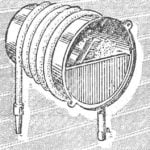 FROM THE OLD BUCKET
a zealous owner any thing you will find to the respective application. Bot and leaky old bucket can still serve as a shelf, being strengthened through the bottom wall of the barn or...
