 In the design business, like any other form of creativity, a person often have to take an unpaved path. This path is always difficult; it is only one who is fluent in the ways, methods and means of design creativity.
How to achieve this perfection?
Our section “Introduction to design” will help you take the first steps on the path of creation, learn the basic techniques of design work. Rooms 9, 11, and 12, 1974, you learned how to develop General technical requirements, as previously calculated basic parameters of the technical device. Today Pasha topic — the choice of a method of transmitting force from the engine to the propeller. So…
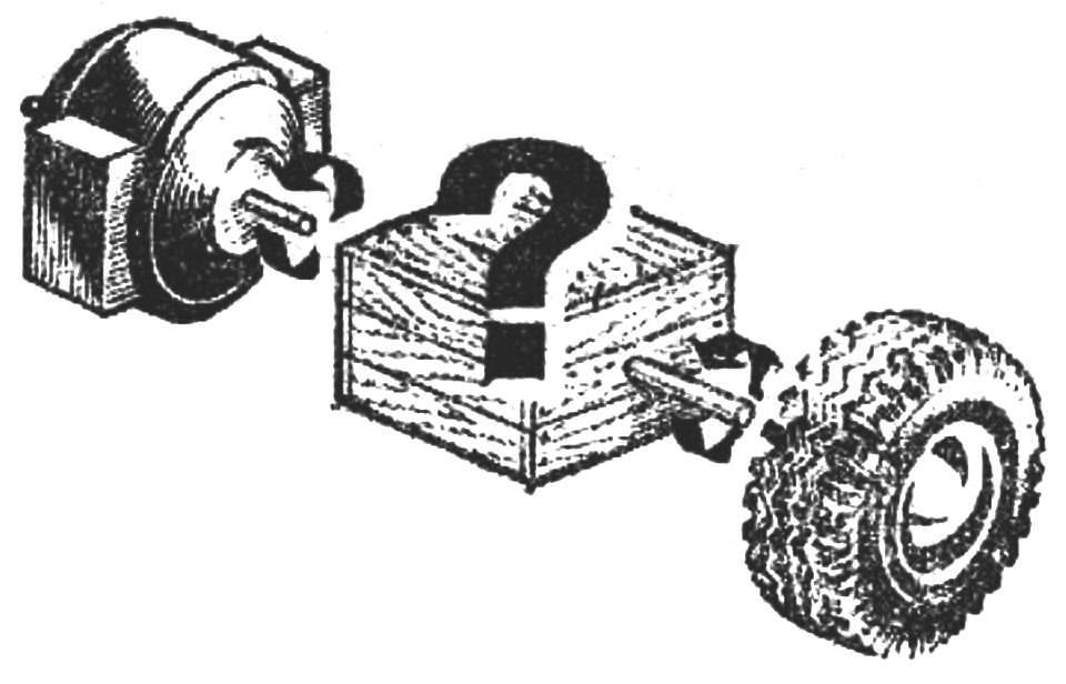
Now we have to develop the design of a mechanism that would allow to transmit the rotary motion of the motor shaft to the wheel. Thus the speed of rotation should be present in each of the above variants of the transport device.
Let’s start with a simple example. You want to set in motion the wheel using the motor, but without intermediate mechanisms. In this case, it is sufficient to connect their shafts with each other: the wheel will spin at the same speed as the rotor of the electric motor. The rotation speed can be adjusted by changing voltage. But with decreasing rpm will decrease and the engine output shaft.

In order to reduce speed without reducing motor power, it is necessary to apply different transmission mechanisms. Such devices, where we have used various principles of transmission — mechanical, electromagnetic, hydraulic and others — there are a great many.
Some of them are shown in figure 1. The main design parameter in these devices is the gear ratio I is the ratio of the speed of rotation of the driving wheel n1 to the speed of rotation of the driven wheel n2:
i=n1/n2
The transfer of rotational friction (friction gear) is the ratio equal to:
i = n1/n2=D2/D1,
where D2 is the diameter of the driven wheel, and D1, the leading.
In gear using the gear wheels (gears):
i = n1/n2=Z2/Z1,
where Z2 — number of teeth of the driven wheel, Z1 — host.
From this relation it follows that to reduce (increase) the number of revolutions of the driven wheels several times, respectively as many times to increase (reduce) its diameter, and the gear — number of teeth.
If you use one pair of wheels, it is called single stage; two pair — two-stage, etc multi-stage gear OBS = i1·i2·i3…in where i1, i2, i3, etc.— the gear ratios for the individual steps.
Now we define the number I for the transmitting mechanisms for the three considered variants of technical devices, and the results will be issued in the form of a table.

Call additional job requirements transmission mechanisms for this technology.
In the first embodiment, it is necessary that the motion of the wheel is stopped almost simultaneously with the stop of the engine.
This condition is most fully to use in the transmitting mechanism of the worm gear. For her I is defined as the ratio of the number of teeth of the worm wheel Z2 to the number of threads (threads) of the worm that is
i = Z2/Z1.
At i=12, it is advisable to use a worm with a number of taps from 1 to 6.
Take a number of hits equal 1 (so the worm can pick up a set of the “Designer”) and determine the number of teeth of the worm wheel is necessary to provide the desired wheel speed.
According to the formula
i = n1/n2=Z2/Z1
find:
Z2 = Z1·n1/n2=1·7500/600
Thus, the transmitting mechanism for ensuring that specified in option 1, the rotation speed of the wheel may consist of single-stage worm gear with single-start worm and worm wheel to the number of teeth is equal to 12 (Fig. 2, a).
In variant II (on school grounds) the termination of the movement can be more fluid.
i = i1·i2=(Z2/Z1)·(Z4/Z3)
In this case, the transmitting mechanism, it is possible to use a cylindrical gear with straight tooth. Since i = 14, it is advisable to use two pairs of gears, that is
i = i1·i2=(Z2/Z1)·(Z4/Z3).
but from the table we know that
i =n1/n2=14000/100=14/1.
Now we can pick up the transmission number of stages:
i = (Z2/Z1)·(Z4/Z3)=14/1=2/1·7/1.
But the number of teeth of the gear may not be less than 6, so found the ratio should increase to 6 times:
i = (Z2/Z1)·(Z4/Z3) = (2/1·7/1)·6=12/6·42/6.
Therefore, Z1=6, Z2=12, Z3=6, Z4 = 42 (Fig. 2, b).
A transferring mechanism model of the lunar Rover (variant III) must provide the transfer from i = 90, hence, it is possible to use a multi – stage pole ] bulb gear or the combined transmitting mechanism, which includes other ways of transmission, e.g. a worm, friction.
You can try to pick up the finished gear from the mechanisms that are produced by the industry for toys. The most appropriate of them can be the gear for toys with inertia motors. The diameter of the flywheel in the mechanism is 40 mm and the gears have numbers of teeth, respectively, Z1=6; Z2=18 and Z3=6; Z4= 18.
This gear on first gear it is convenient to use force trepnya, and next leave the spur gear.
PA motor shaft in this case, you need to wear a rubber tube so that the thickness of the shaft tube was approximately equal to 4 mm (Fig. 2). Tag gear ensures the desired speed of motion of the model. To improve the reliability and maneuverability of motion of the model (turns right, left, circle) will use two engines and two gearboxes, one on each side.
In our models we have abandoned the use of couplings. Driving wheel (gear, worm, pulley) of the first stage is mounted on the motor shaft and the driven gear of the last stage gear is fixed on the wheel shaft.
The bearings and the bearings for axles and shafts can be standard or self-made. These questions in relation to our models specified in the decision of technological problems at the stage of manufacture and Assembly of the mechanism.
The design of the transmitting mechanism may be over. But what if ready-made gears there, and to make them in a mug often impossible? Figure 3 shows several varieties of homemade transmission mechanisms. Any of these programs work reliably, even if we assume slight inaccuracies in manufacture. Try to apply these ideas in practice. We offer you to continue independent development of self-propelled transport carts (see “modelist-Konstruktor”, 1974, No. 11). Identify transmission mechanisms for these devices.
Literature:
A guide for the inventor and innovator. M.—Sverdlovsk, Mashgiz, 1963.
Artobolevsky I. I. Mechanisms in modern technology. M., “Nauka”, 1971.
Kovalev N. A. Theory of mechanisms and machine parts. M., “Higher school”, 1974.
Collection of tasks and examples of calculation at the rate of machine parts. M., “Engineering”, 1974.
Children’s encyclopedia, vol. 5, ed. 2. M., Prosveschenie, 1965.


