SIBERIAN UNICYCLE

SIBERIAN UNICYCLE
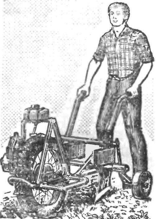
I live in Krasnoyarsk region. I have my own house and a small farmland. Every spring, homeland is the garden, I wondered how ease is to mechanize this hard work. So we decided – we need to build the motor-plow.

The engine I have was from a motorbike.
 
The frame I made from half-inch water pipes. Welded to it a bracket of the drive wheel (corners 40X25 mm and a length of 100 mm), support gear (steel plate 4 mm thick), cross with sockets for working bodies and shelves fuel tank chainsaw “Ural”.
 
The engine is mounted in the fork tubes of the frame at point reinforced lengths of pipes. That it does not overheat, equipped with a forced cooling system is simple in design centrifugal fan. Its a homemade impeller attached to the end of the engine crankshaft. This machined axle and replace it regular the screw that secures the drive gear to the clutch. Brought the axle out through the hole in the clutch cover, put the impeller, pulley starter, and nut (bushing impeller and a pulley are connected by a pin preventing the mutual turning). The fan shroud that directs the air flow on the fins of the cylinder, riveted to the clutch cover.
Torque from the engine, run with the help of rubberized cord, a chain is passed to the reducer, which is used as the cut from the bike frame, and modified pedals. The essence of refinement in the following. Pedal was removed, and the sprocket (48 teeth) on the right end of the shaft left. The opposite end of the adjusted output 10-bevel sprocket engine D5: bored through the seat and keyway, tapped.
 
Fig. 1. The layout of the motor-plow
 
Fig. 1. The layout of the motor-plow:
 
1 – frame, 2 – engine 3 – fuel tank 4 – wheel with grousers, 5 rail to adjust the depth of plowing, 6 – carrier rollers, 7 ploughs, 8 – handle control with clutch lever, 9 – clamp lever detent clutch, 10 – control stick, throttle, 11 – cross, 12 – reducer, 13 – launch pulley, 14 fan guard, 15 – location of ballast box.
 
Fig. 2. Frame
 
Fig. 2. Frame:
 
1 — rails, 2 — left slot, 3 — Central socket, 4 — sleepers, 5 — pole reducer, 6 — place mounting of the engine. 7 — bracket of the drive wheel, 8 — clip, ballast box, 9 — shelf fuel tank.

 
Fig. 3. Right wheel bracket
 
Fig. 3. Right bracket wheels:
 
1 — utorok, 2 — tension bolt, 3 — retaining wall.
 
Then welded a steel plate with a thickness of 4 mm to the reducer bushing and attach it with four bolts, MB to a support on the frame.
 
Gear chain goes to the wheel of the moped “Verhovina”, covering the pedal sprocket of a Bicycle, which I welded to the standard sprocket wheel. So it does not slip during ploughing, attached to the lid 14 grundsatzes – corners 20Х30Х60 mm M6 Bolts for fastening took with broad round heads, to prevent damage to the camera.
On the left side of the motor-plow on the clamp pipe 1/2″ placed wooden ballast box, which is loaded when plowing to increase the weight of the unit – improve the adhesion with the soil.
 
Working bodies secured in sockets on the crossbars: one to the left, another in the center. The first socket is suitable for plough (somewhat modified Coulter), and the second – legs of the cultivator or plough-mouldboard. Initially I worked with the plough, fixed in the center, letting wheel over the snow. However, it was difficult to sustain the direction. Had to make a left slot, and the wheel to put on the furrow.
 
Fig. 4. Forced cooling system
 
Fig. 4. The cooling system:
 
1 impeller 2 casing impeller, 3 — duct, 4 — a casing of the cylinder.

 
Fig. 5. Completion of the engine
 
Fig. 5. Finalization of the engine:
 
1 — Carter, 2 — pinion clutch 3 — clutch cover, 4 — special axle washer 5 — bushing of the impeller, 6 — pin, 7 — starting pulley, 8 — cone nut.

 
R and p. 6. Reducer
 
Fig. 6. Gear:
 
1 — shaft, 2 — lock pin sprocket, 3 — foot star, 4 — base plate, 5 — pedals, 6 — segment dowel, 7 — sprocket engine D5, 8 — nut.

 
R and p. 7. Grouser.
 
R and S. 7. Grouser.
 
At the side of the strut I is attached rollers, which regulate the depth of plowing. They give additional stability to the unit, reduce the load on the hands. Right rink should be a little wider than the left, because rolling on arable land. When I work as a cultivator, it is mounted on the center rollers off completely to avoid damage to planting.
 
Handle the clutch and throttle of the carburetor taken from the bike “Voskhod”, the cables of the scooter. For handle grip drilled in the handrail through hole Ø4 mm, in which is inserted the clamp fixing lever in the released position when the engine is started).
 
Motor-plow good plow light soil to a depth of 12-18 cm greater the depth begins to affect the lack of engine power and low weight.
KUZNETSOV, Kansk

Recommend to read

  • RAKE-GRAPPLERAKE-GRAPPLE
    Cleaning up fallen leaves is one of the everyday work in any garden. And basic gardening tool and an ordinary rake. Nemurasete seems to be the case, but... to remove the foliage even...
  • The SMALLEST V12 ENGINEThe SMALLEST V12 ENGINE
    A Spanish engineer named patalo were collected 12-cylinder V-shaped engine, which, he believes, is the smallest such engine in the world. The engine consists of 261 element, made of...