The watercraft we would like to introduce to readers can quite rightly be classed as a small vessel. After all, what else would you call a pair of versatile self-propelled floats that can easily be used both as water skis and as a two-seater pleasure catamaran.
As can be seen from the drawings, each float is a miniature boat with a power unit comprising a battery, electric motor and propeller.
The displacement of one float is about 140 kg, which allows not only fitting it with a power unit but also lets the “skier” lean on just one float when needed without fear of it submerging.
Of course, those interested in this unusual watercraft are free to choose their own construction method. However, the lightest hull will result from laying up fiberglass in a mold or on a plug using epoxy or polyester resin. This approach also means the amateur builder only has to maintain the hull shape and dimensions precisely once—when making the plug or mold.
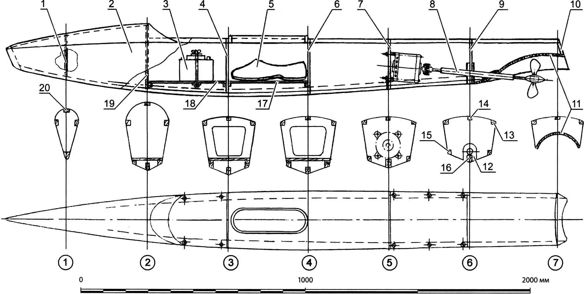
Self-propelled float construction:
1, 4, 6, 7, 9, 10, 19 – bulkheads (plywood s8); 2 – float shell (fiberglass); 3 – 12-volt battery 30–40 Ah; 5 – “boot”; 8 – power unit; 11 – tunnel (fiberglass and epoxy layup); 12 – pad (plywood s10); 13, 14, 15, 20 – stringers (pine battens 20×20); 16 – keel (pine batten 30×50); 17, 18 – sole (plywood s8)
To make the plug, cut a set of frames from about 6 mm plywood and fix them keel-up on a chipboard panel using wooden blocks and bracing battens according to the theoretical hull drawing given here.
Then fill the space between the frames with cement-sand mortar. To lighten the plug and reduce cement use, scraps of boards are fixed between the frames so that the mortar layer is no more than 30 mm. After the mortar sets, the plug surface is leveled with filler and sandpaper, then painted with two or three coats of automotive enamel with sanding between coats.
The hull shell is laid up from fiberglass and epoxy resin. Depending on fiberglass weight, five to eight layers are needed. Before molding the shell, apply a release layer of wax paste or car polish to the plug.
Mold the hull without long breaks; otherwise the shell may delaminate and leak in use. Note that epoxy cures in two to four hours at room temperature with the usual resin-to-hardener ratio of 8:1.
After the resin cures, the shell is removed from the plug and a frame of keel (pine batten 20×50 mm), frames (6 mm plywood) and stringers (pine battens 15×15 mm) is glued inside the future float hull.
Bases of 8–10 mm plywood are then fitted between frames 2 and 3 and between frames 3 and 4—the first for the battery and the second for the “skier’s” foot—if the floats are to be used as self-propelled water skis.
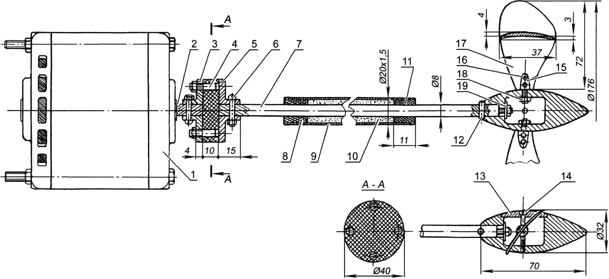
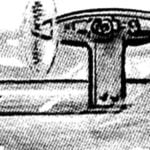
1 – electric motor; 2 – motor shaft; 3, 5 – coupling flanges; 4 – pin; 6 – lock bolt with nut; 7 – propeller shaft; 8, 11 – stern tube bushings; 9 – stern tube; 10 – grease; 12 – locking pin; 13 – fairing cap; 14 – cap screw; 15 – propeller blade bushing; 16 – rivet; 17 – propeller blade; 18 – blade retaining nut; 19 – hub retaining nut
The power unit of each float is based on a 12 V battery of up to 30 Ah together with an electric motor from a car cooling system (e.g. VAZ-2109) used to drive the fan.
The stern gear consists of a stern tube with PTFE or textolite bushings—plain bearings—pressed in at both ends, and the propeller shaft.
The space between the shaft and stern tube is filled with grease such as CIATIM. The motor shaft and propeller shaft are connected by a rubber-metal coupling: two steel flanges each with two steel pins, and a 10 mm thick rubber disk with four holes for the pins.
Calculating propeller parameters precisely is quite difficult—it is better to make a variable-pitch propeller. Its basis is a streamlined hub turned from duralumin on a lathe, with a slot and three holes inside: one for mounting the hub on the propeller shaft, the others for the blade bushings. The blades are 4 mm sheet duralumin; profile convex-concave, asymmetric, rounded at the leading edge and sharp at the trailing edge. Blade bushings are steel; blades are attached with aluminum rivets.
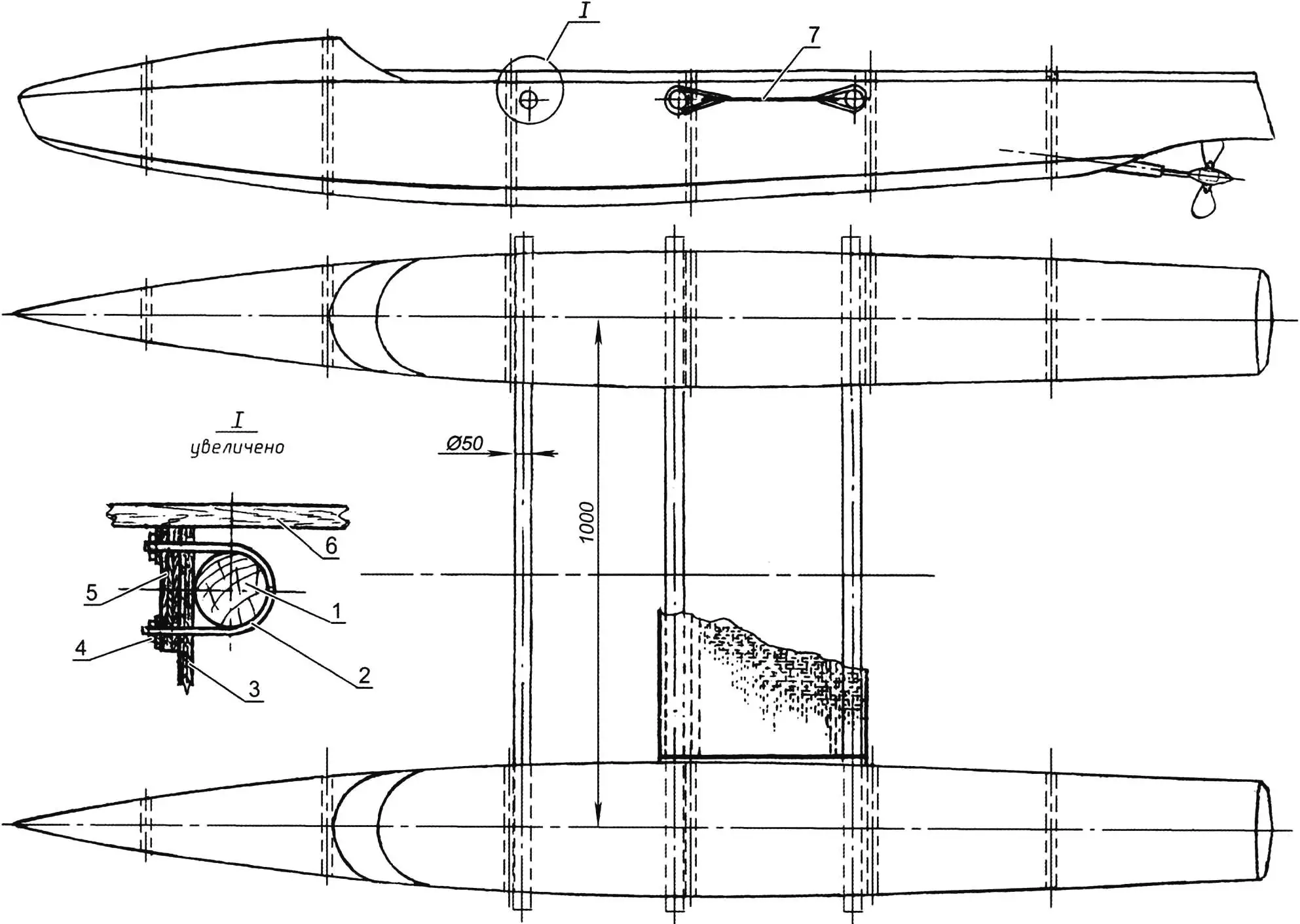
1 – crosspiece (wood, 50 mm dia. bar); 2 – half-clamp (steel, 6 mm dia. rod); 3 – frame; 4 – M6 nut with washer; 5 – pad (plywood s10); 6 – stringer; 7 – seat (canvas)
The best blade pitch is found after launching the float, by test runs at different propeller blade angles. Thrust can be measured with a simple dynamometer—a household spring scale. Given the low speed of the float, maximum thrust corresponds to the best blade angle.
After finding the best angle, the hub is closed with a cap secured by a long M5 screw.
The upper parts of the floats are molded on a separate plug using the same method as the float shells. Between frames 5 and 6, a coaming—vertical rim of the hatch for mounting and servicing the motor—is formed from 10×40 mm pine battens. The battery compartment between frames 2 and 3 has a similar hatch. Hatch covers must seal well to keep water off the electrical gear. Wiring should be in double-sleeve cable and the control switch connector must be waterproof.
The compartment between frames 3 and 4 is for the “skier’s” foot—a plastic boot, of the kind used for garden work, is screwed to the plywood sole. To keep water out of the float hulls when moving, you can sew sleeves from thin synthetic jacket fabric with elastic at the top and fix them to the hatch coamings.
The electric skis are controlled by two toggle switches, each with three positions: “forward”, “stop” and “reverse”. If suitable toggles are not available, a homemade switch can be made.
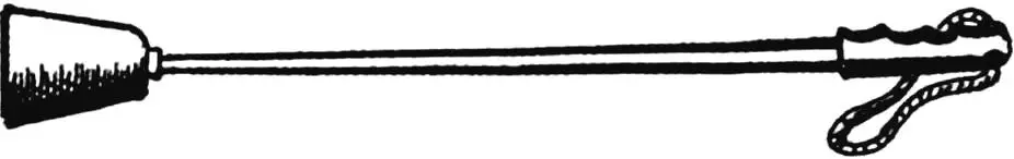
At first it helps to connect the ski-floats with two lines at the front and back so the distance between them does not exceed half a meter—otherwise the floats will drift apart and the “skier” will end up in the water. A pair of ski poles with conical plastic flower pots instead of the usual baskets at the bottom will help you keep your balance and can also help you reach shore if the power unit misbehaves.
As mentioned above, the pair of self-propelled floats can be turned into a compact electric pleasure catamaran. Simply connect the floats with a bridge of three round wooden crosspieces 50 mm in diameter. They are attached to frames 2, 3 and 4 with half-clamps bent in a U-shape from 6 mm steel rod with M6 thread on both ends. A piece of heavy canvas stretched over the two rear crosspieces makes a comfortable seat.
The catamaran is controlled the same way as the skis—by switching the electric motors.
Modelist-Konstruktor No. 3’2013, I. MNEVNIK
Recommend to read
 JUST LIKE THE CHAMPIONS
Good modelers! Almost all of the many sports classes they have and the same subclass designed for students. Equipment from the "juniors" easier, more accessible, and to treat her in the...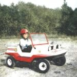 LITTLE MICRO-CAR “BUDDY”
Little micro-car "Buddy" machine... for kids. It was created in a laboratory experimental simulation and design Club for young technicians Novosibirsk Akademgorodok. Despite its small...
