Once upon a time, there was a popular TV show “You Can Do It” where craftsmen talked about the designs they had created. Perhaps it was there that information about air-cushion vehicles first appeared. And publications in the “Modelist-Konstruktor” magazine pushed many enthusiasts, including ours from Angarsk (mainly amateur fishermen), to build such machines with their own hands. The air-cushion vehicle was tempting with its apparent simplicity, promising good technical characteristics. In reality, however, its design turned out to be a tough nut to crack, which only a few managed to crack.
In the early days in the Angara region, bulky and metal-intensive machines appeared, far from technical and aesthetic perfection. These, so to speak, “ugly ducklings” never acquired the valuable qualities of an air-cushion vehicle, disappointing their creators to the point of complete disenchantment.
Gradually, the air-cushion vehicle boom passed, and only a few of the most persistent continued to build and somehow operate their designs.
I also had the temptation to test my skills on an air-cushion vehicle, but, weighing the possibilities, I postponed work on it until better times.
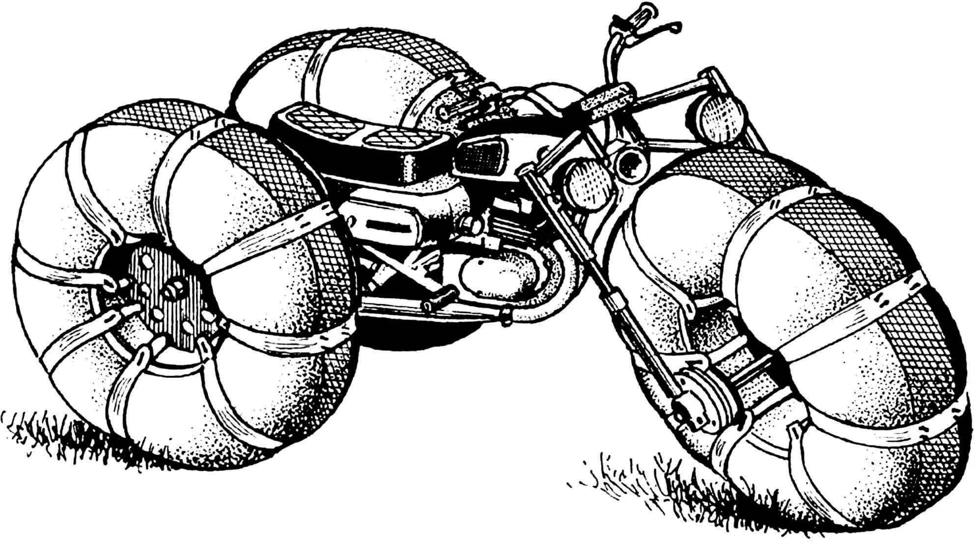
Several years later, at the urgent request of an acquaintance of mine, a passionate amateur fisherman, I built an air-cushion vehicle for him. The acquaintance provided me with a “Voskhod-3M” motorcycle on the condition that by the summer season, the air-cushion vehicle should easily transform back into a motorcycle. Thus, based on the “Voskhod”, “Losharik” appeared.
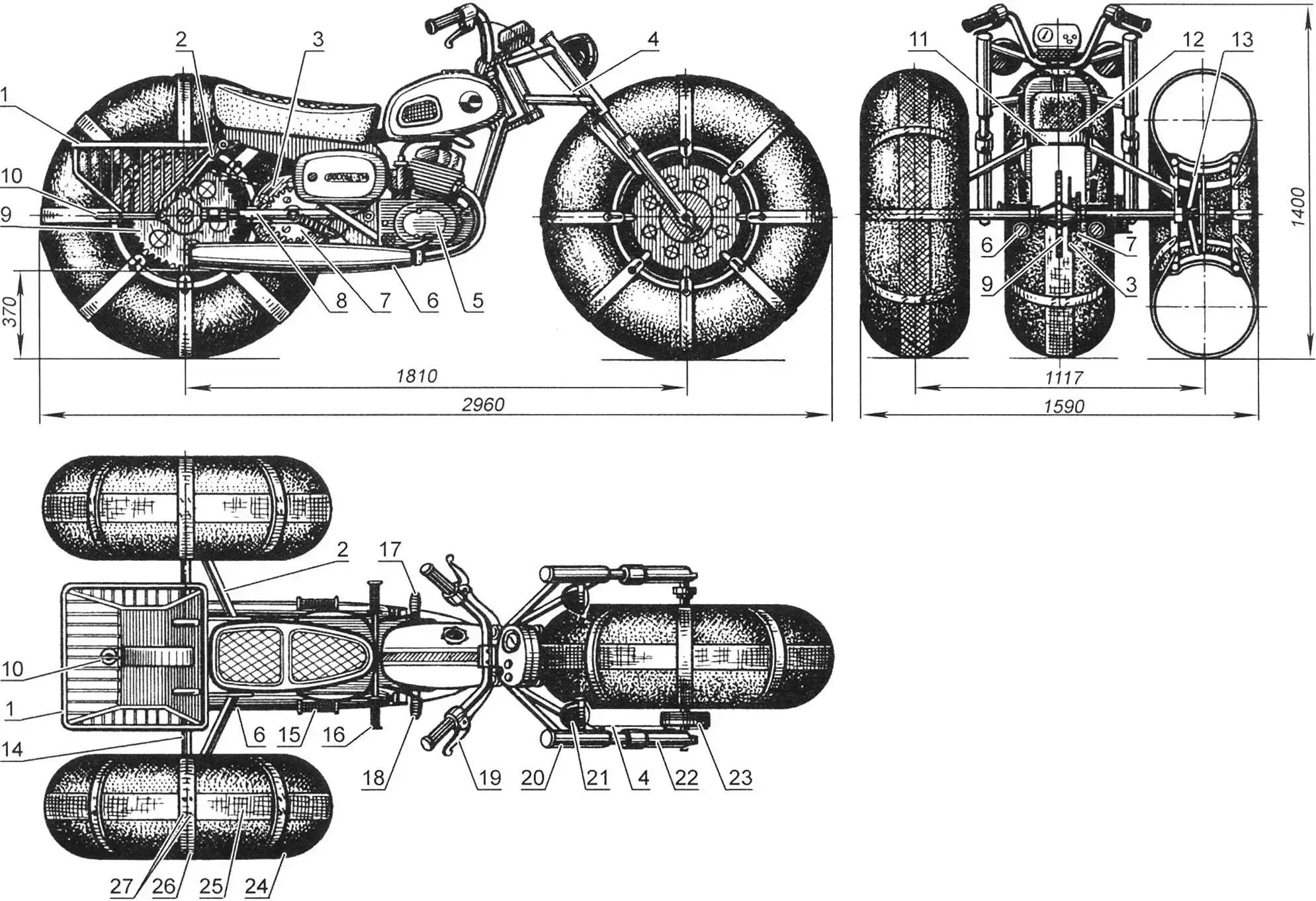
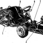
1 – luggage rack (not shown on rear view); 2 – struts; 3 – brake disc; 4 – front wheel brake cable; 5 – engine (from “Voskhod-3M” motorcycle); 6 – mufflers; 7 – large intermediate reducer sprocket; 8 – rear suspension frame; 9 – drive sprocket; 10 – eye bolt; 11 – spacer; 12 – motorcycle frame seat post; 13 – spoke (tube 18×2, 4 pcs. per wheel); 14 – rear axle shaft; 15 – passenger footrest (removed); 16 – driver footrest; 17 – gear shift pedal; 18 – rear wheel brake pedal; 19 – front wheel brake lever; 20 – front wheel fork; 21 – headlight; 22 – fork leg; 23 – brake drum; 24 – pneumatic tire (not shown on side view); 25 – longitudinal band; 26 – transverse band; 27 – band connection brackets
This is a three-wheeled high-mobility vehicle on low-pressure pneumatics measuring 1200×500 mm. It is designed for solo rides or with a passenger. Rated for a maximum load of 180 kg (weight of driver, passenger, and cargo in the luggage rack). The air-cushion vehicle moves quite well on loose snow up to 450 mm deep at an average speed of 25 km/h. In spring and autumn, the air-cushion vehicle easily overcomes ice edges, is not afraid of mud and ice. The traction qualities of “Losharik” allow it to pull sleds with a load of up to 150 kg behind it.
“Losharik” is an open vehicle. It operates without problems at air temperatures down to -25°C. The driver is protected from hypothermia by warm clothing, as well as a removable windshield and shields (not shown in the drawings).
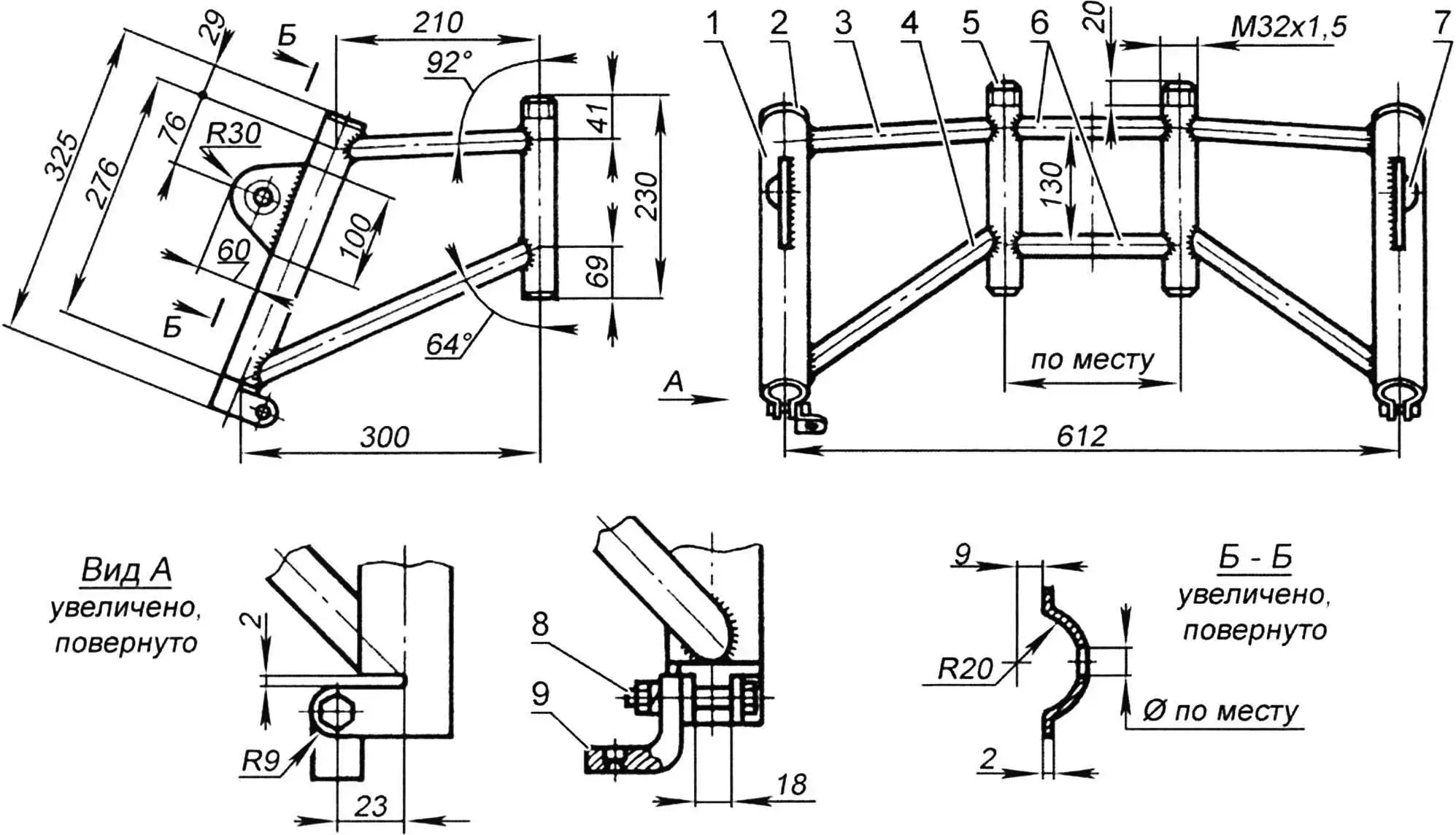
1 – housing (tube 42×2); 2 – plug (sheet s2); 3,6 – crosspieces (tube 22×2); 4 – strut (tube 28×2); 5 – bearing sleeve (tube 32×3); 7 – headlight bracket (sheet s2);
8 – bolt M10х1.25; 9 – brake cable housing stop (from motorcycle)
The air-cushion vehicle engine does not have forced cooling, but the possibility of its cooling by a 12 V DC electric fan connected to the engine generator through a rectifier bridge is provided.
Despite some shortcomings of the design scheme, this air-cushion vehicle in skilled hands is generally a decent machine.
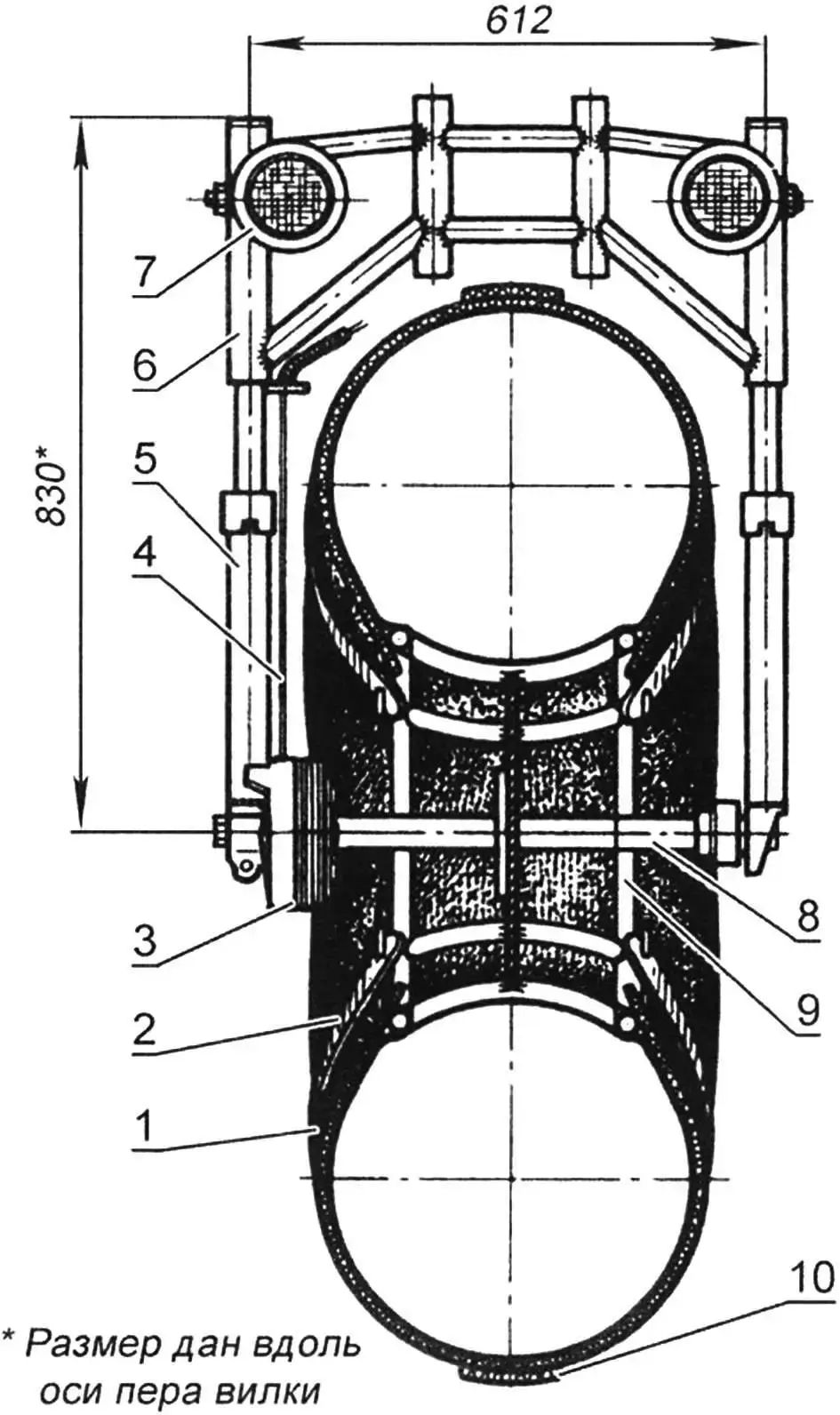
1 – tube 1200×500; 2 – transverse band (rubber-fabric tape 60×10); 3 – brake drum (from “Voskhod-3M” motorcycle); 4 – brake cable; 5 – fork leg (from “Voskhod-3M” motorcycle); 6 – fork frame: 7 – headlight; 8 – hub; 9 – wheel; 10 – longitudinal band (fire hose)
I will begin the description of “Losharik” with the device of its front fork. The fork frame is welded from tubes of different diameters. The housings at the bottom have clamps for fixing telescopic shock absorbers from “Voskhod-3M” fork legs. Wooden blocks approximately 80 mm long are inserted inside the housings, against which the shock absorbers additionally rest, and plate brackets for mounting headlights are welded on the outside. In addition, a stop for the brake cable housing is screwed to the clamp of the right housing.
The housings are connected to the frame load-bearing tubes by crosspieces and struts. These tubes are inserted instead of fork legs into the motorcycle steering column bridges. In the upper bridge they are fixed with nuts, and in the lower one – with tie bolts.
1 – wheel axle mounting bolt; 2 – wheel axle; 3 – right fork leg; 4 – brake drum; 5 – hub; 6 – left fork leg; 7 – bearing 60204 (2 pcs.); 8 – spacer washer (s5); 9 – bolt M8 (6 pcs.)
A long axle-bolt of the front wheel hub is inserted and fixed in the ends of the fork legs, as on a motorcycle. The hub itself is a steel tube with a diameter of 43×2 mm with flanges and a bearing cup for bearing 60204 welded to it. The wheel disc is attached to the central flange with M8 bolts, and the brake drum from “Voskhod-3M” is attached to the side one (the brake mechanism is borrowed from another motorcycle). It is connected to the lever on the handlebar by a standard cable in a housing.
All three wheels of the air-cushion vehicle are structurally identical. The only difference is that the front one is screwed to the hub flange with eight M8 bolts, while the rear ones are attached to their hubs with steel rivets 8 mm in diameter and additionally reinforced with spokes – four per wheel.
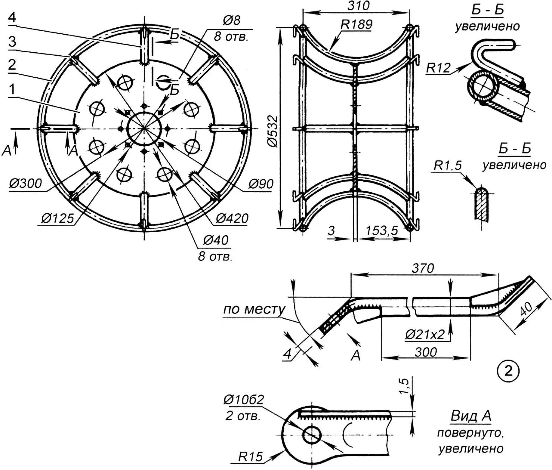
1 – disc (St2, sheet s3); 2 – rim (tube 18×2.2, 2 pcs.); 3 – hook (rod Ø8, 16 pcs.); 4 – cradle (tube 18×2, 8 pcs.)
The wheel rims and cradles are made from 18×2 mm diameter tube, the discs are made from 3 mm thick sheet steel. To reduce weight, 40 mm diameter holes are drilled in the discs. Sixteen hooks made from 8 mm diameter rod are welded to each wheel. Transverse bands are attached to them – pieces of rubber-fabric tape 60 mm wide and 10 mm thick, holding the pneumatics on the cradles. Longitudinal bands are made from canvas fire hose. At the intersections with the transverse ones, they are “stitched” with steel brackets made of 3 mm diameter wire. However, it is possible to operate the air-cushion vehicle without bands on the front wheel. If necessary, the pneumatics can be reinforced – put duplicates made from the same tubes cut along the smaller diameter on them.
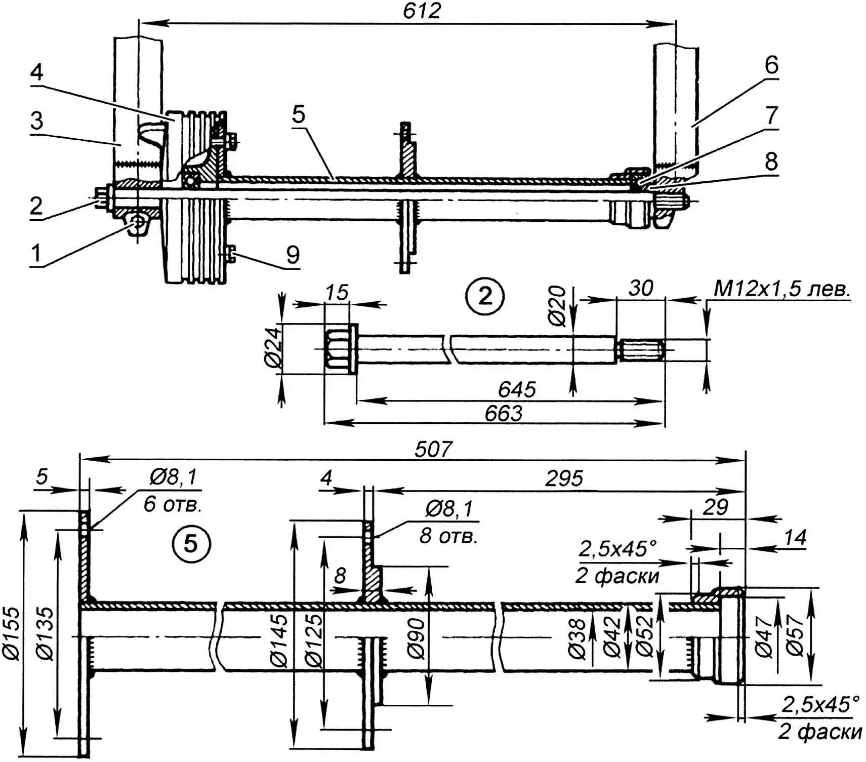
The intermediate reducer and rear axle are mounted on a special U-shaped rear suspension frame welded from 32×3 mm diameter tubes. This frame consists mainly of two side members and a cross beam reinforced on top with a plate. It is attached to the motorcycle frame in the same way as the standard rear suspension swingarm.
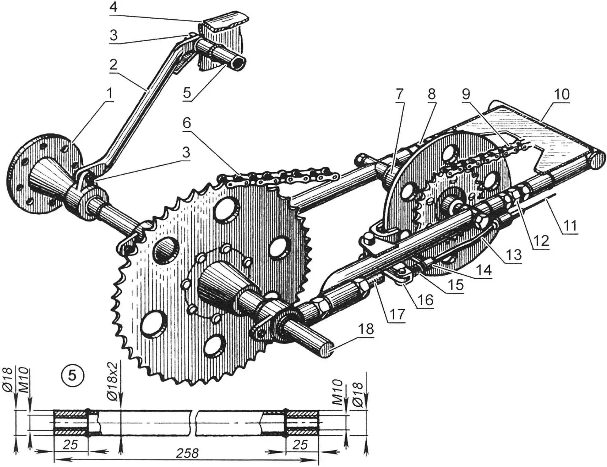
1 – left wheel hub; 2 – strut (tube 21×2, 2 pcs.); 3 – bolts M10 (4 pcs.); 4 – motorcycle frame seat post; 5 – spacer (tube 18×2); 6 – drive chain (Ø19.05); 7 – intermediate reducer; 8, 12 – double-ended intermediate drive chain tensioner bolts (M18x1.5 and M18x1.5 left); 9 – intermediate drive chain (t = 12.7); 10 – rear suspension frame; 11 – brake cable; 13 – cable housing; 14, 16 – brake levers; 15 – compression spring; 16 – drive chain tensioner bolt (M18x1.5, 2 pcs.); 18 – rear axle shaft
The side members are adjustable, as they have devices for tensioning the intermediate drive chain. The rear ends of the side members are hot-rolled and equipped with threaded sleeves for mounting the rear axle and tensioning the drive chain. Approximately in the middle, bearing sleeves for the intermediate shaft axis are welded into both side members. In addition, there are brackets on the left for mounting the cable and levers of the rear wheel brake mechanism.
The intermediate drive chain tensioning devices are two double-ended bolts with left and right M18x1.5 threads and locknuts. The drive chain tension is adjusted by two M18x1.5 bolts welded to the central bearing cups of the rear axle.
The intermediate reducer hub is made together with a small sprocket (z = 18, t = 19.05). A 300 mm diameter brake disc and a large sprocket (z = 40, t = 12.7) are attached to the hub flange with six M8 countersunk head bolts. Two 204 bearings are pressed into the hub, which rotate on a 12 mm diameter axis and are lubricated through a grease fitting installed on the hub between the small sprocket and the brake disc. The bearings are isolated from external dirt penetration by felt seals.
The rear axle design is simple: a long shaft rotates in four 207 bearings. The shaft has three keyways for prismatic keys of the wheel pair hubs and drive sprocket, as well as two grooves for spring retaining rings.
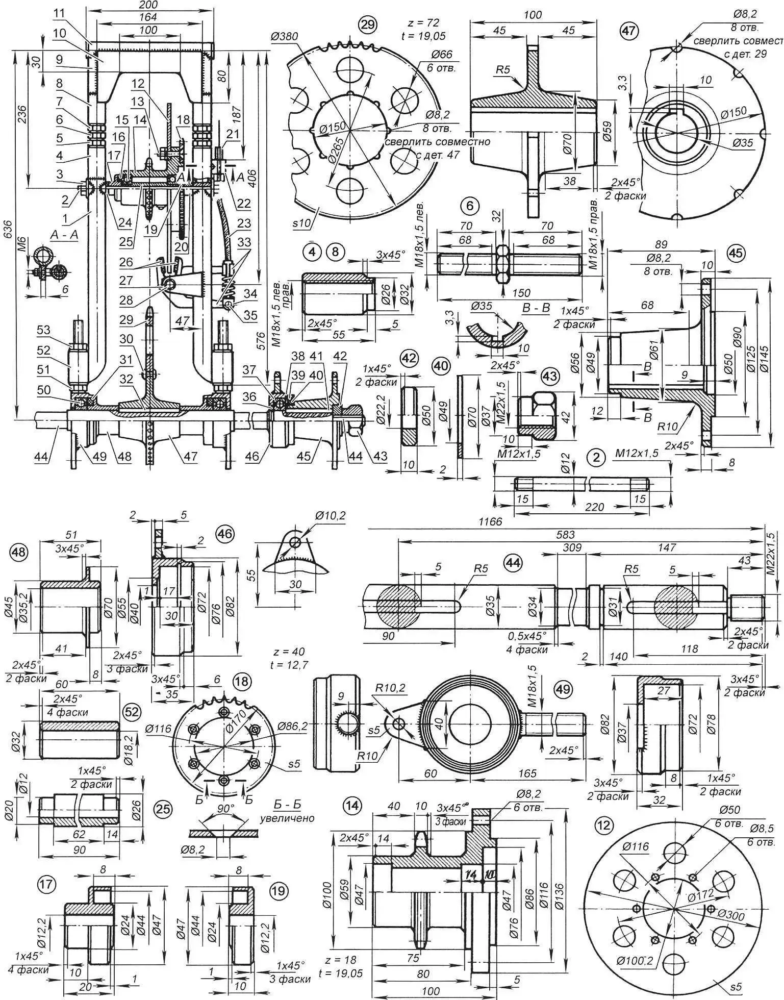
1 – left side member (tube 32×3); 2 – intermediate reducer shaft (steel 20, rod Ø12); 3 – shaft mounting nut M12x1.5 (2 pcs.); 4 – frame coupling M18x1.5 left (2 pcs.); 5 – locknut M18x1.5 left (2 pcs.); 6 – double-ended intermediate drive chain tensioner bolt (M18x1.5 and M18x1.5 left, 2 pcs.); 7 – locknut M18x1.5 (2 pcs.); 8 – frame coupling M18x1.5 (2 pcs.); 9 – frame spacer (tube 32×3, 2 pcs.); 10 – frame plate (steel, sheet s2); 11 – frame cross member (tube 32×3); 12 – brake disc; 13 – bolt M8 (6 pcs.); 14 – intermediate reducer hub with small sprocket (z = 18, t = 19.07); 15 – bearing 204 (2 pcs.); 16, 31, 39 – seals (felt, 6 pcs.); 17,19 – seal housings; 18 – large intermediate reducer sprocket (z = 40, t = 12.7); 20 – adjustment sleeve (tube 24×5.9, L8.5); 21 – brake cable adjustment coupling; 22 – adjustment coupling housing; 23 – brake cable housing; 24 – adjustment washer (tube 24×5.9, L3.5); 25 – spacer sleeve; 26 – brake lever pads (asbolatex cardboard on epoxy glue); 27 – brake mechanism axis (bolt M8); 28 – brake mechanism bracket upper shelf (steel, sheet s5); 29 – drive sprocket (z = 72, t = 19.05); 30 – rivet (Ø8, 8 pcs.); 32 – prismatic key (steel 40, 8x10x100); 33 – brake levers; 34 – brake cable end; 35 – pin (steel 40, Ø6); 36, 38 – retaining rings (4 pcs.); 37, 50 – bearings 207 (4 pcs.); 40 – seal cover (2 pcs.); 41 – prismatic key (steel 40, 8x10x80); 42 – thrust ring (2 pcs.); 43 – shaped nut M22x1.5 (2 pcs.); 44 – rear axle shaft (steel 20); 45 – rear wheel hub (2 pcs.); 46 – external bearing cup (2 pcs.) 47 – drive sprocket hub; 48 – shaped spacer sleeve (2 pcs.); 49 – central bearing cup (2 pcs.); 51,53 – locknuts M18x1.5 of left drive chain tensioner bolt; 52 – rear axle mounting sleeve-bracket (2 pcs.)
Bolts are welded to the front of the central bearing cups, simultaneously serving for drive chain tension and mounting to the rear suspension frame, and eye bolts for attaching the luggage rack are welded to the rear. Shaped spacer sleeves with flanges are put on the shaft between the drive sprocket hub and the inner bearings, which hold felt seals in the cups.
Eye bolts for mounting the lower ends of tubular struts are welded to the external bearing cups. The upper ends of the struts are screwed to the seat post through holes intended for mounting rear turn signal lights.
Bearings are lubricated with “Litol-24” once every three years after partial disassembly of the units. The drive sprocket (z = 72, t = 19.05) is from an agricultural unit, lightweight. It is attached to the hub with 8 mm diameter rivets, preheated in a forge.
The rear wheel brake mechanism is disc-type, caliper type. The brake levers are installed in a bracket, the shelves of which are welded to the right side member. Pads made of asbolatex cardboard with a high coefficient of friction on steel are glued to the lever cheeks with “epoxy”. The cable from the brake pedal passes through a short housing located between the adjustment coupling and the front brake lever. The adjustment coupling is located in a housing screwed to the bracket under the right side member.
The presented brake mechanism is quite complex to manufacture. If possible, it is easier to use a hydraulic disc brake drive from “Izh-Planeta-5” or “Izh-Yupiter-5-01” motorcycles, respectively adjusting the mounting bracket and pedal to the main brake cylinder drive.
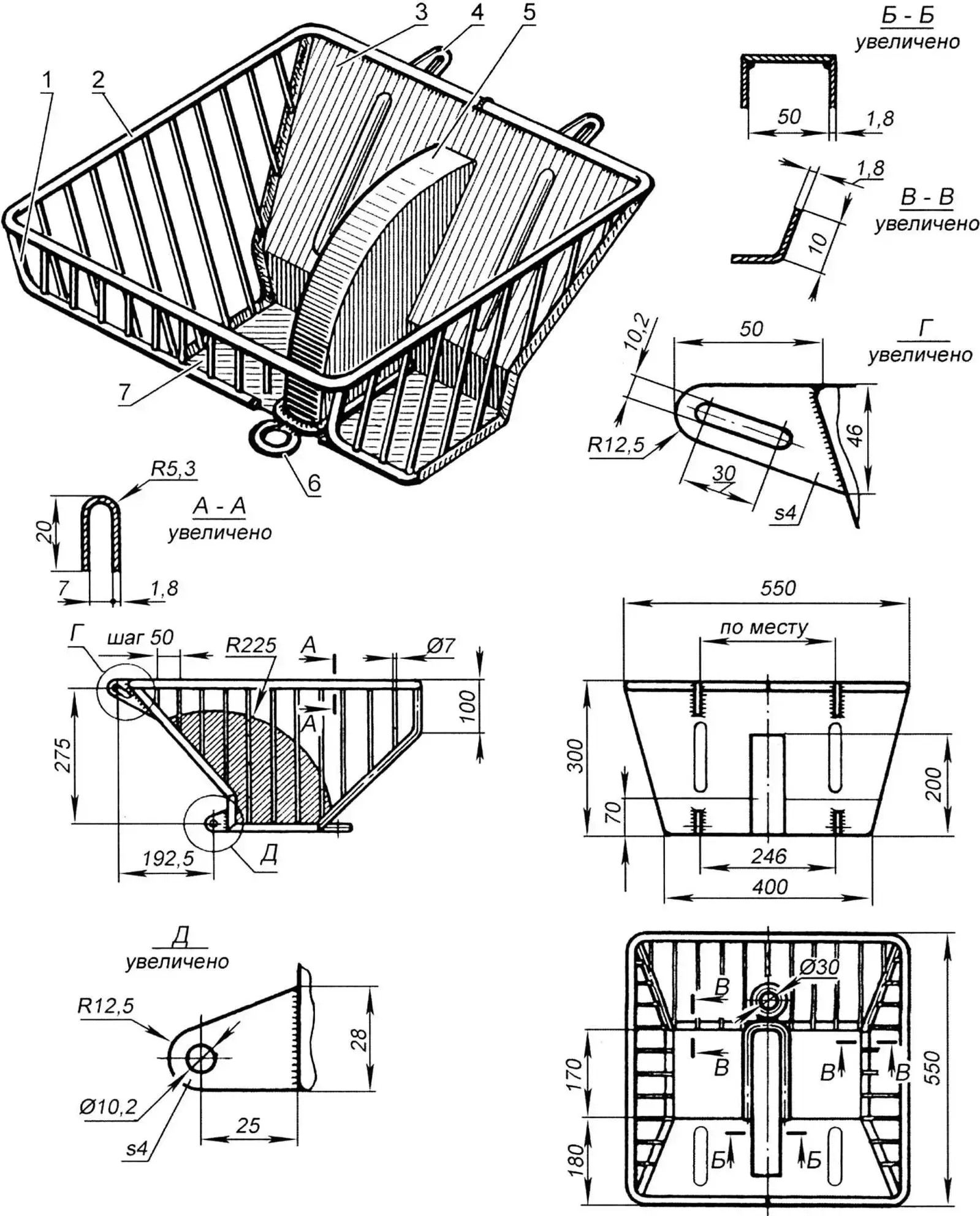
1 – lattice (rod Ø7); 2 – rim (sheet s1.8); 3 – wall (sheet s1.8); 4 – eye bolt (sheet s4, 4 pcs.); 5 – drive sprocket housing (sheet s1.8); 6 – eye bolt (rod Ø12); 7 – bottom (sheet s1.8)
The luggage rack is made half-lattice so that snow does not accumulate in it. The main materials of its construction are a 7 mm diameter steel rod and 1.8 mm thick sheet steel. The inclined front wall and bottom are welded together with a box-shaped housing that protects the chain drive from accidental entry of foreign objects. The luggage rack is quite strong and rigid and allows transporting not only a decent load. There is an eye bolt at the rear, serving as a towing device.
The luggage rack is attached to the air-cushion vehicle with M10 bolts at four points: at the top – to the seat post, at the bottom – to the eye bolts of the central bearing cups of the rear axle.
All newly manufactured units were painted bright red nitro-enamel paint after edge cleaning, so that when forced to move on public roads, the air-cushion vehicle would visually stand out in traffic. Then the units were installed on the “Voskhod-3M” motorcycle frame, from which everything that was not required for the operation of the air-cushion vehicle was previously dismantled: fenders, front fork, rear suspension swingarm with shock absorbers, etc. The electrical equipment was not modified.
And a little about safety. The air-cushion vehicle is named “Losharik” not by chance: due to the springy tires, it has a temper. Therefore, I recommended to my acquaintance when riding it to avoid sharp turns and sudden braking (the first is fraught with overturning, the second – with band breakage), and to overcome snow banks and other similar obstacles on the move and at a right angle. The recommendations paid off: after my acquaintance “broke in” “Losharik”, it became a truly indispensable vehicle for him.
V. PETROV
Recommend to read
 CHAMPION CARDS
Circle carting of the Palace of pioneers of the Bauman district of Moscow one of the leading in our country. The team of the Palace is constantly among the strongest kart USSR. But a...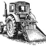 WINCH TRACTOR
Large forestry in the country today are equipped with powerful and high-performance appliances. However, there is a lot of auxiliary operations, the performance of which has not yet been...
