Many rural amateur constructors quite rightly consider the motor winch the most promising soil‑tillage unit. It is not without drawbacks, however. The main one is the need each time to drag a fairly heavy plow from the end of the furrow back to the start, while shifting the motor winch itself by the inter‑furrow distance. The reason is that in this case the power unit and the tillage implement are separate.
There is a way out, though. Nothing prevents combining the motor winch and the plow into a single unit. True, it will no longer be a universal mechanism capable of plowing, harrowing, cultivating, and serving as a lifting device for building a house or digging a well—just a plow. A motor‑driven plow.
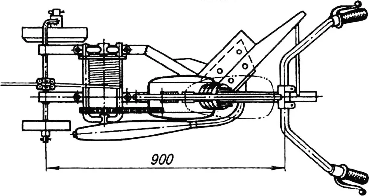
The winch mounted on it uses a cable to pull itself toward an anchor. At the end of the furrow you only need to turn the plow around, and to the start of the new furrow you move only the anchor. Then you just engage first gear, release the clutch lever, and “give it gas.”
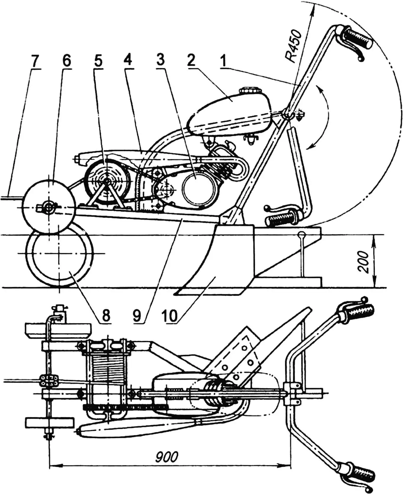
1 — plow control handles (steel tube 22×2.5); 2 — fuel tank; 3 — V-50 engine; 4 — muffler with exhaust pipe; 5 — cable drum; 6 — landside wheel; 7 — steel cable Ø 4…5; 8 — furrow wheel; 9 — motor plow frame; 10 — plow
The basis of such a motor unit is a plow built to the type of a classic horse-drawn one. It has a reinforced V-shaped frame welded from rectangular steel tubes 40×60 mm (round tubes 40–50 mm outer diameter can also be used). The landside and moldboard are made from 3 mm steel sheet, the slide from 30×30 mm angle. For the share, hardened quality steel is best—e.g. a circular saw blade about 4 mm thick. The furrow wheel, 300 mm in diameter, and the landside wheel, 160 mm, are welded from sheet steel. The wheel axle is bent from 20 mm diameter steel bar.
On top of the plow frame is the engine mount—an arc-shaped bracket on which the V-50 engine is mounted (the type once used on “heavy” mopeds). Its power is modest, only about 2 hp, but the pull at the drum is quite sufficient for plowing a vegetable plot for potatoes.
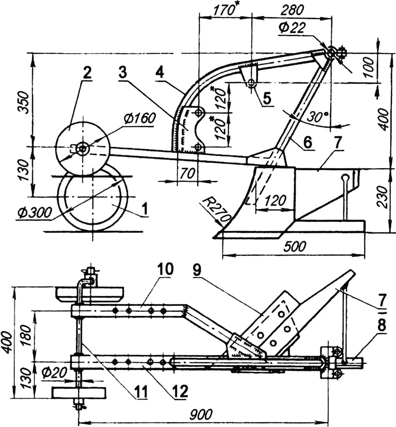
1 — furrow wheel; 2 — landside wheel; 3, 5 — engine mounting lugs (steel sheet s3); 4 — engine-mount arc (steel tube 40×2.5); 6 — stanchion (steel tube 40×60 or 50×3); 7 — moldboard (steel sheet s3); 8 — slide (steel angle 30×30); 9 — share (blank—circular saw blade s4); 10, 12 — motor plow frame (steel tube 40×60 or 50×3); 11 — furrow and landside wheel axle (steel bar Ø20)
The fuel tank is mounted in the standard way—as on a moped. In principle, a plastic can of about 5 L will do; you only need to fit a fuel tap from any motorcycle or moped into its bottom.
As is known, the V-50 engine is not designed to run without cooling by the oncoming air stream. Organizing forced cooling is not too difficult: remove the generator cover and on the flywheel (which is also the rotor) fix an impeller cut from duralumin, and bend a simple guide shroud from sheet metal.
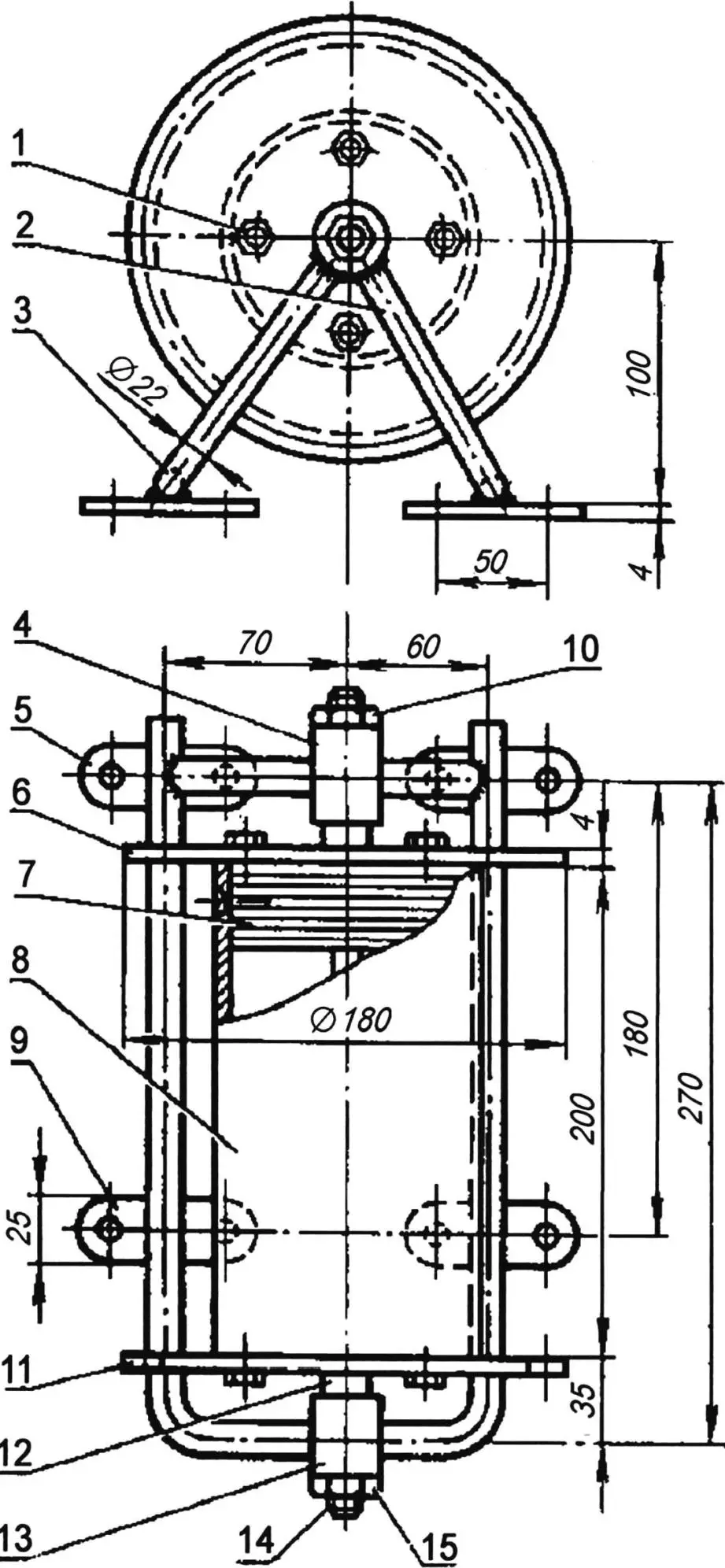
1 — M8 bolt for sprocket and drum flange; 2, 3 — drum brackets (steel tube 22×2.5); 4, 13 — bushings (steel tube 22×3); 5, 9 — drum mounting pads; 6 — drum flange (steel sheet s4); 7 — hub (from moped or light motorcycle wheel, 2 pcs.); 8 — drum (steel tube or steel sheet s2.5); 10, 15 — drum axle nut; 11 — sprocket (z=41); 12 — bushing (nylon or textolite, 2 pcs.); 14 — drum axle
The plow control handles are made from 22 mm diameter tube sections and fitted with moped (or motorcycle) engine controls: throttle (right), clutch and gear lever (left). The left handle also carries the decompressor lever for stopping the engine. Both handles are clamped on the plow frame and can be adjusted for operator height and comfort.
The winch drum is assembled from two moped wheel hubs, with a large-diameter tube section—ready-made or bent and welded from 3 mm sheet—fixed by six M6 screws. Use a larger sprocket—e.g. a front chainwheel from an adult bicycle with z = 41. Its thickness is a bit low, so it is better to use the standard sprocket as a template and cut a new one from thicker material (steel or hardened duralumin).
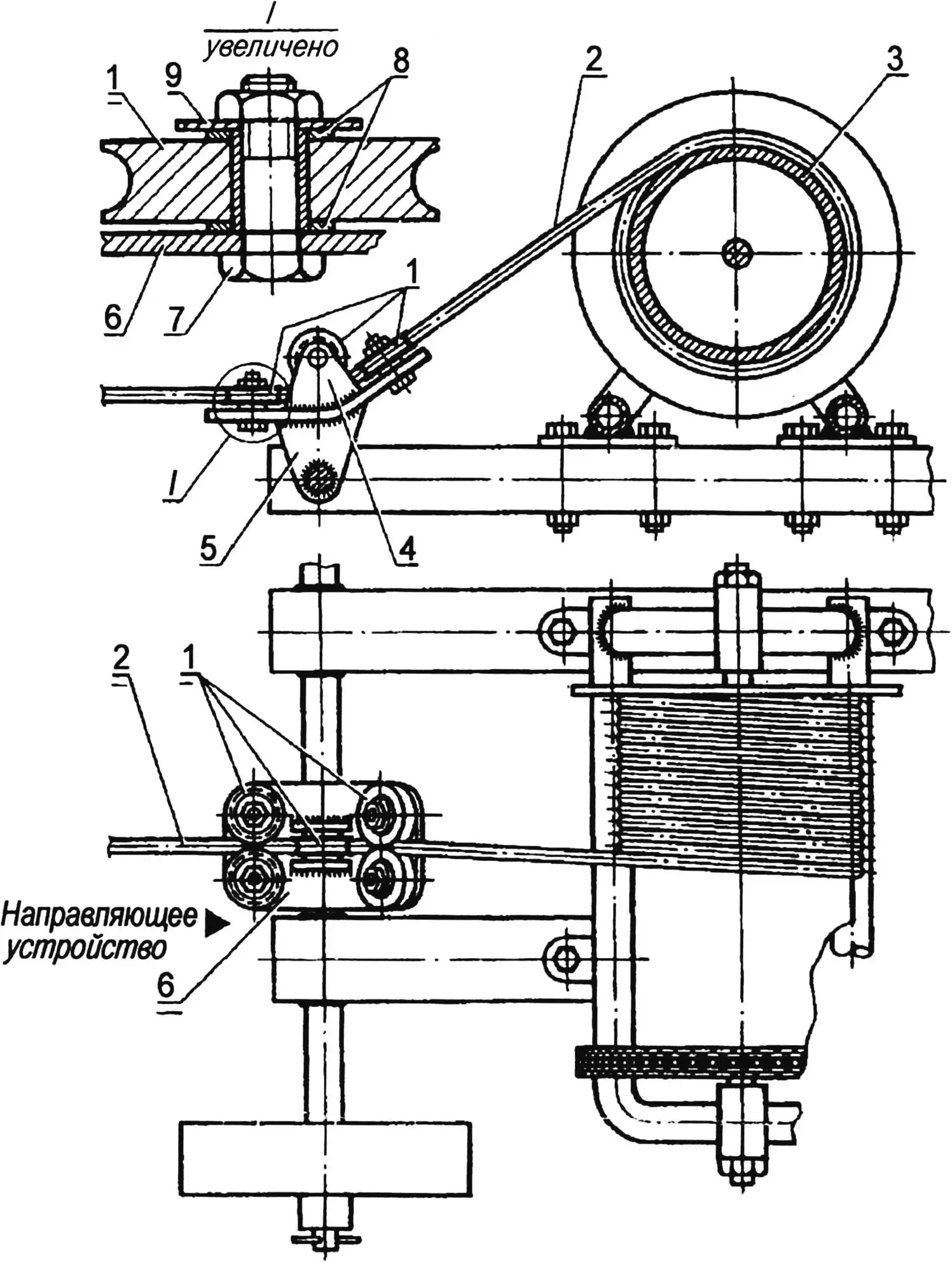
1 — rollers (steel); 2 — steel cable Ø4…5; 3 — winch drum; 4 — fork (steel sheet s3); 5 — bracket (steel sheet s3); 6 — base (steel sheet s4); 7 — M10 bolt with nut; 8, 9 — washers
At the front of the motor plow, on the wheel axle, is the cable guide with rollers through which the tow cable runs. It consists of a base plate with five rollers: four on the base and a fifth, whose axis is perpendicular to the others, in a fork welded to the base.
The anchor for securing the cable is simple in design. The anchor blade (the part that goes into the ground) resembles a trenching shovel blade. The steel blank is 2 mm thick. The crossbar—the above-ground part—is 16 mm diameter steel bar; an 8 mm bar eye for the cable is welded to the crossbar.
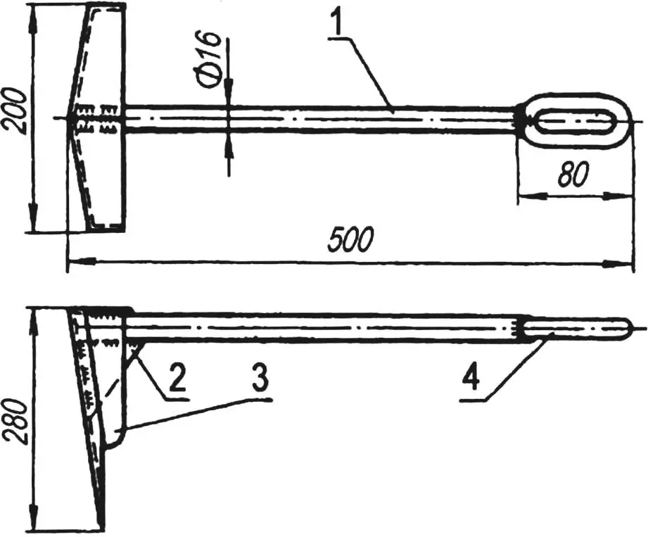
1 — spindle (steel, bar Ø16); 2, 3 — stiffening ribs (steel, sheet s3); 4 — stirrup (steel, bar Ø16)
Note that the anchor design depends greatly on the soil. In some cases you may need a larger anchor area or even a different cable anchorage—e.g. a special “auger” of 16–18 mm bar screwed into the ground with a bar. Experience with such augers for tying down aircraft shows they are practically impossible to pull out of the ground.
«Modelist-Konstruktor» No. 4’2011
Recommend to read
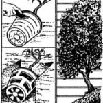 IN THE GROUND — BUT FROM THE POT
The one who had the opportunity to admire the sprawling tent amazingly beautiful flowering shrub clematis, will not stand the desire to have such a miracle and the outside the house or...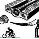 TREAT THE PEDAL…
Bike pedals used to put a metal screw cap to protect the bearings from contamination. Now, instead, use the plastic plugs, which are often lost. Rescue plastic or nylon tubes from...
