The kart design (Fig. 1) has no complex units requiring high qualifications of performers and can be replicated in technical clubs of schools or at young technicians’ stations that have a lathe and gas welding. The kart construction must be carried out in a certain sequence. First, the front and rear axles are manufactured, and then the frame is welded.
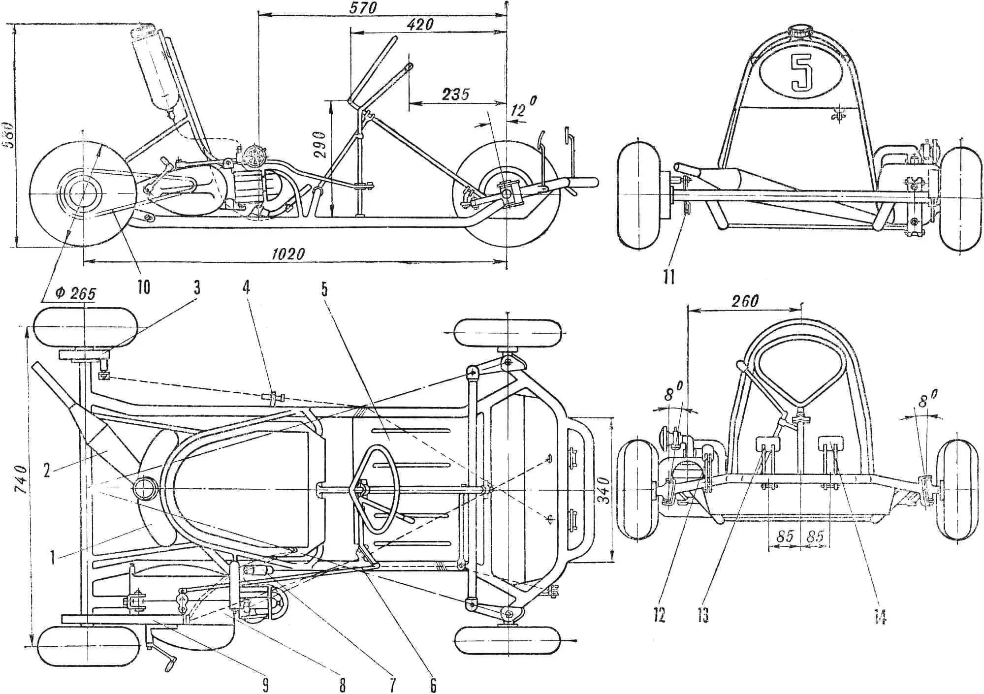
Fig. 1. General view (layout drawing):
1 — fuel tank; 2 — exhaust silencer; 3 — rear brake; 4 — adjustable brake cable stop; 5 — aluminum floor (ribbed stiffening ribs are visible); 6 — gear shift lever rod; 7 — ignition coil; 8 — engine (“Jawa-50”), 9 — chain guard; 10 — motorcycle roller chain (K-125); 11 — rear brake lever; 12 — throttle pedal; 13 — brake pedal; 14 — clutch pedal.
FRONT AXLE (Fig. 2) consists of beam 10, two lugs 9 and steering knuckles of the front wheels (Fig. 3).
The steering knuckle (see Fig. 3) consists of axle 6 and kingpin bushing 9, turned on a lathe. The axle is fitted to the bushing at an angle of 98° and welded.
The steering arm 8 (see Fig. 2) is bent from sheet steel 1.5 mm thick in such a way that in cross-section it has a U-shaped profile, after which it is fitted to the steering knuckle so that the knuckle axis forms an angle of 110° with the axis drawn through the center of the kingpin bushing and the middle of the steering arm.
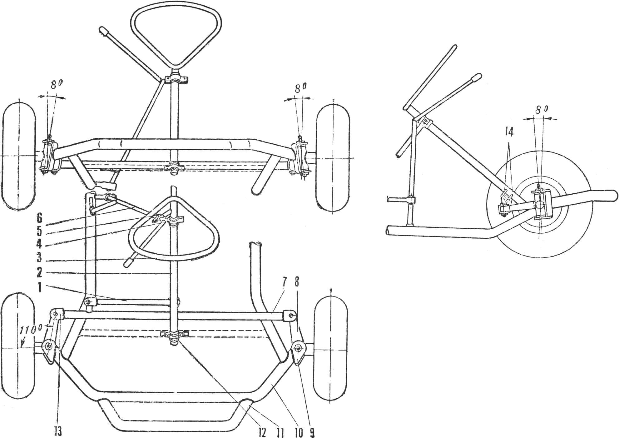
1 — steering rod (tube 30KhGSA Ø 12 mm); 2 — steering column (tube 30KhGSA Ø 16 mm); 3 — steering wheel (tube 30KhGSA Ø 12 mm); 4 — steering column bearing (textolite); 5 — gear shift lever bracket (steel 3); 6 — gear shift lever axis (tube 30KhGSA Ø 12 mm); 7 — tie rod (tube 30KhGSA Ø 12 mm); 8 — steering arm (steel 3, δ = 2 mm); 9 — front axle lug (steel 3, δ = 4 mm); 10 — front axle beam (tube 30KhGSA Ø 25 mm); 11 — bumper (tube 30KhGSA Ø 25 mm); 12 — steering column bearing (textolite); 13 — steering joint lug (steel 3. δ = 2 mm); 14 — steering arm (steel 3, δ = 4 mm).
The tail ends of the steering knuckle axles have threads. Steering joint rings are welded to the ends of the steering arms. Support bushings 11 (see Fig. 3), kingpin 7 and hub 13 are turned on a lathe. In this case, the holes of the support bushings are made smaller than the kingpin diameter. It is desirable to drill a lubrication channel in the kingpin, make transverse holes for the exit of lubricant to the support bushings and cut threads for installing grease fitting 8. The support bronze bushings are pressed into the kingpin bushing and machined to the kingpin size with a reamer of the appropriate diameter. Their ends are fitted to the size of the front axle beam lugs so that when the kingpin nut is fully tightened, the steering knuckle rotates easily on the kingpin and has no play.
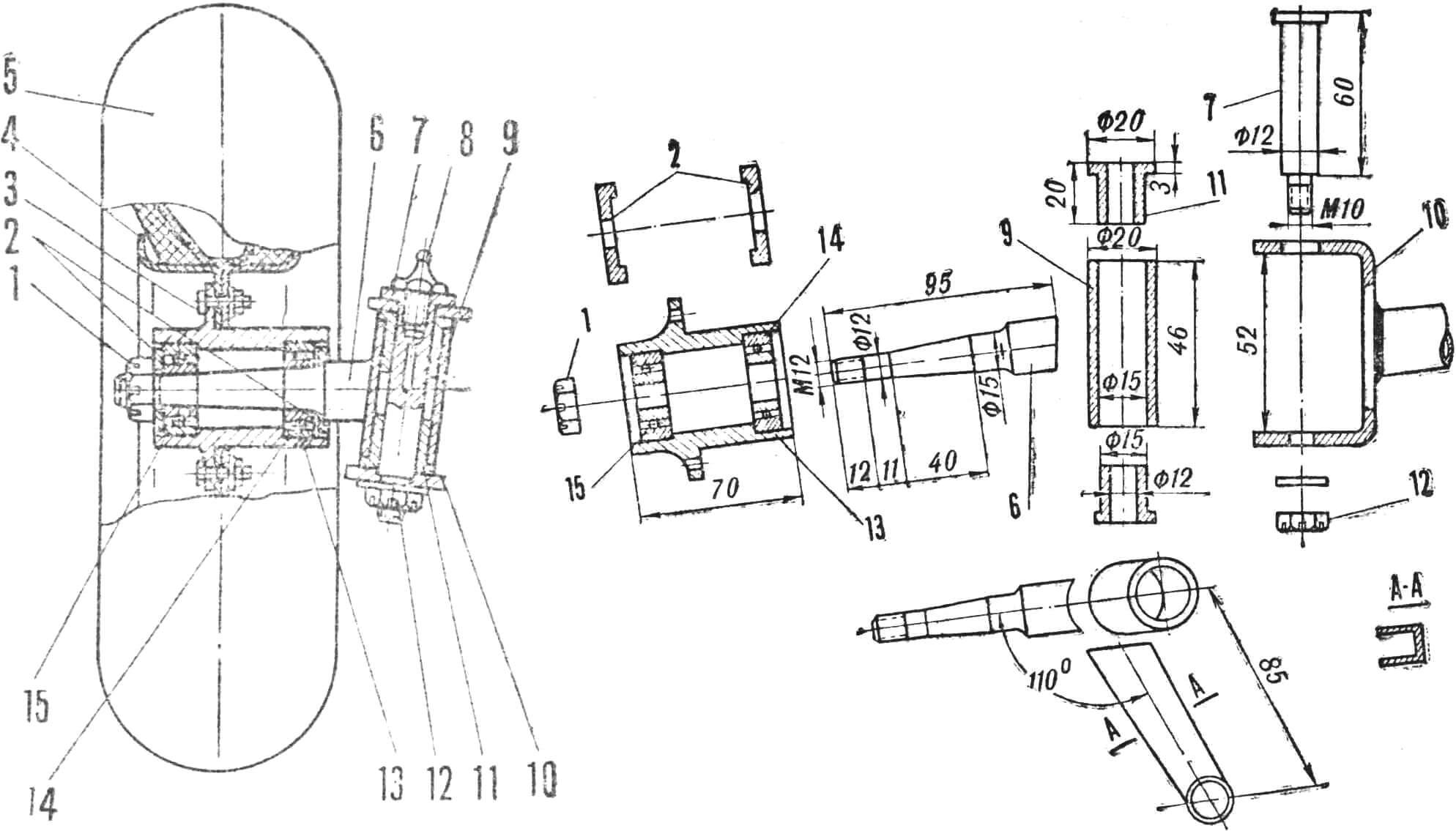
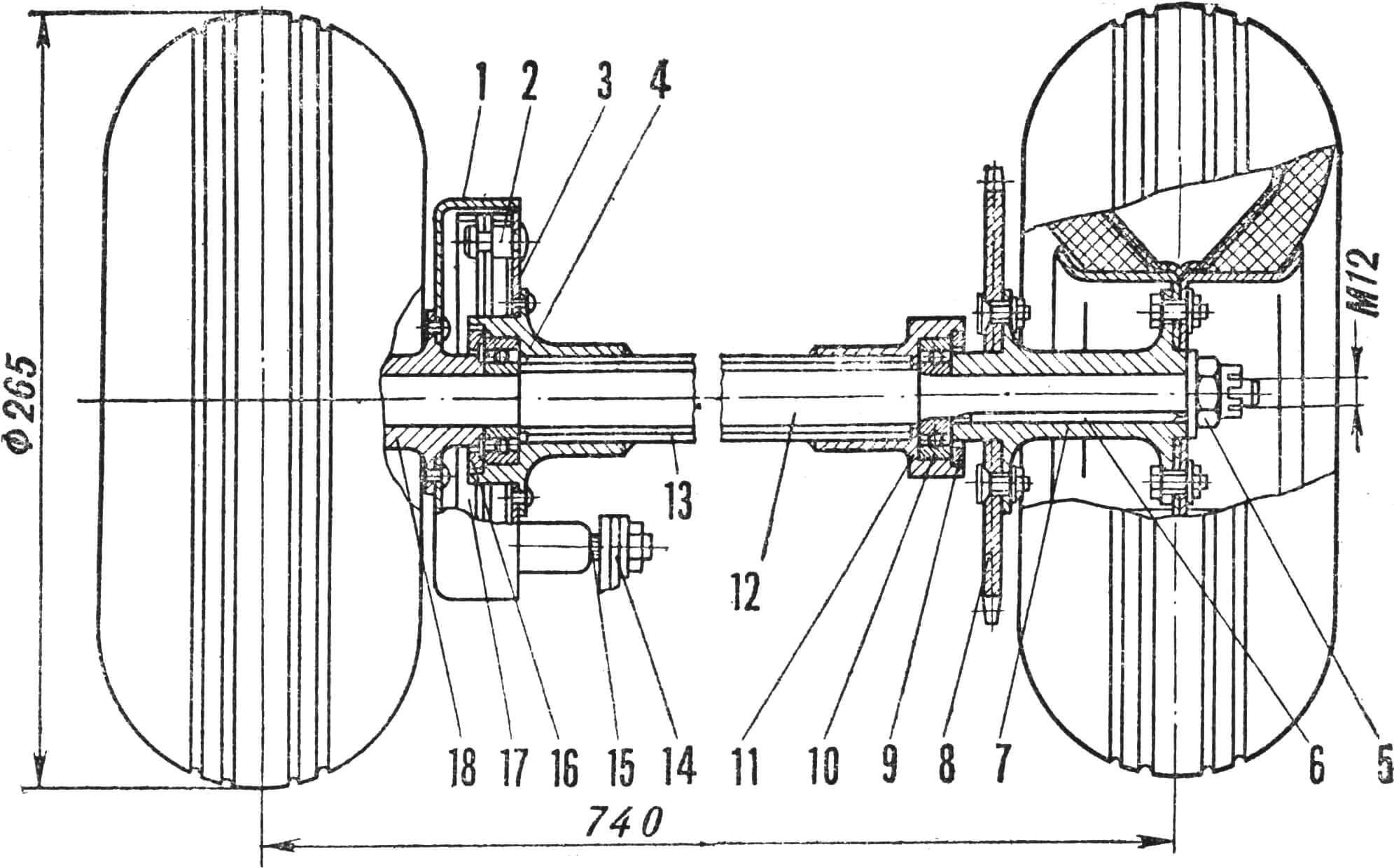
1 — knuckle axle nut M12 (steel 45); 2 — seal washers (steel 3); 3 — disc-to-hub mounting bolt M6; 4 — wheel disc (steel 3 — 1.5 mm); 5 — aircraft tire 225X110; 6 — knuckle axle (18KhNVA); 7 — kingpin (steel 35); 8 — grease fitting; 9 — kingpin bushing (steel 3); 10 — front axle lug (steel 3); 11 — support bushing (bronze of any grade); 12 — kingpin nut M10 (steel 45); 13 — front wheel hub (steel 45); 14 — bearing No. 202; 15 — bearing No. 201.
Bearings No. 202 and No. 201 are installed in the hub 13 seats, which are closed on the outer sides by seal washers. The hub is fixed on the knuckle axle with a crown nut 1, which tightens the inner bearing races. A spacer bushing (not shown in the drawing) is installed between them, the length of which is chosen so that when the knuckle nut is fully tightened, the hub rotates easily on the bearings and cannot shift along their outer races.
WHEEL DISCS 4 consist of two halves. The discs of the front and rear wheels are made from sheet steel 1.5 mm thick on a lathe, extruding according to a template using a roller (see No. 7, 1968). The discs are fastened to the hubs with four M6 bolts, the heads of which are tack-welded.
1 — lug (steel 3); 2 — connecting joint bolt M8; 3 — joint rings (steel 3); 4 — steering arm; 5 — bushing (rubber); 6 — crown nut M8; 7 — tie rod tube.
After assembling the left and right steering knuckles of the front axle, they are connected to the lugs using kingpins. The latter are fitted to the beam (see Fig. 2) of the front axle so that the camber angle of the front wheels is zero, while the knuckle axles will be located horizontally, and the kingpins are inclined inward of the machine by 8°. In addition, the front axle parts must be set before welding so that the kingpin caster angles are 12°.
It must be remembered that the magnitude of the kingpin angles and wheel camber significantly affects the stability and handling of the kart, so the work on their installation must be performed with high accuracy.
STEERING. A closed steering wheel with an angle at the vertex of about 120° and an arm of 200 mm is made from a thin-walled tube Ø 12 mm and welded to the steering column 2 (tube Ø 16 mm and wall thickness of at least 2 mm). The steering column rotates in two textolite sliding bearings 12 and 4, reinforced with steel plates to the kart frame (see Fig. 2).
To prevent longitudinal displacement of the steering column, thrust rings are welded to it, located above the upper and below the lower sliding bearings. (It is necessary to protect the bearings from overheating during welding.)
An arm 14 (see Fig. 2) with an arm of 60—65 mm, consisting of two plates, is welded to the column. The welding location is found after the tie rod and steering rod (thin-walled tubes Ø 12 mm) are manufactured. Practice has shown that the length of the tie rod must be selected during road tests of the machine according to its most stable behavior, so the tie rod must be made adjustable.
A U-shaped lug is welded to one end of the rod, and a steel bushing with an internal M10 thread is inserted into the other and welded to it. A rod 40—50 mm long with the same thread is screwed into the bushing, a locknut is screwed onto it, and another lug is welded to the free end. The lugs have Ø 3 mm holes for connecting joint bolts. A joint for connection with the steering rod is located on the tie rod. The latter consists of a tube, a lug and a joint.
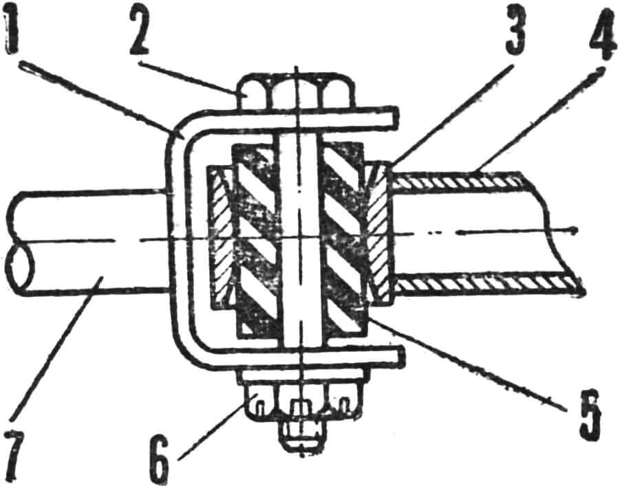
Rubber bushings are installed on all joints (Fig. 4) of the steering mechanism. They have no play and work well when the angles in the joints change.
The steering angle of the steered wheels must be at least 30-35° in one direction, while the gap between the rotating parts of the front wheels and the frame must be at least 5 mm. All connections are assembled using crown nuts and cotter pinned (Fig. 6).
REAR AXLE — closed type (Fig. 5). This design provides greater frame strength, although it somewhat reduces its elasticity. The rear axle Ø 18 mm is made of steel 18KhNVA. The axle tail ends have bearing seats for bearings No. 202, longitudinal keyways for installing keys and M12 threads at the ends.
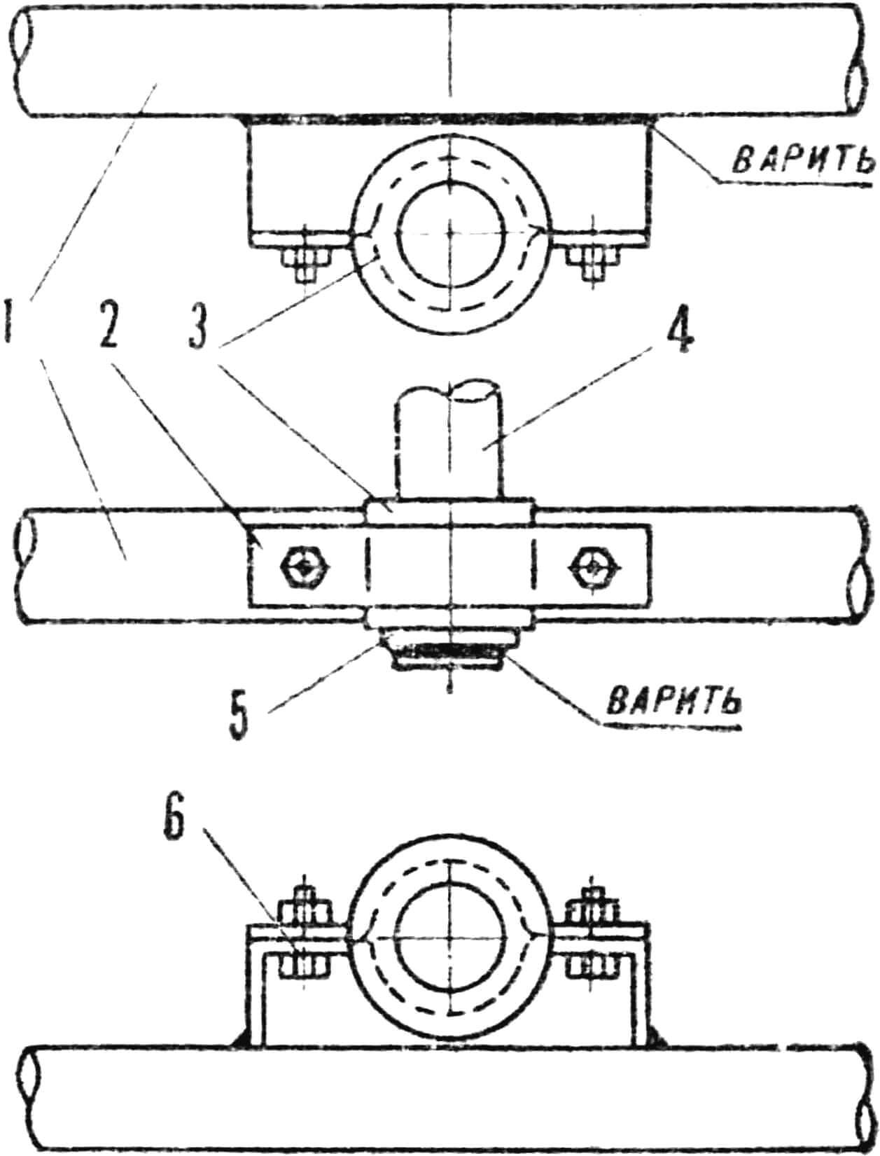
1 — frame crossmember; 2 — plate (steel 3); 3 — sliding bearing; 4 — steering column; 5 — thrust ring (steel 3); 6 — M6 bolt with nut.
Bearing supports 4 and 11 are turned for light press fit on the connecting tube, with the left support having a flange for mounting the brake support disc. The bearings are clamped along the outer race with threaded washers, with the right support and its washer having right-hand threads, and the left ones having left-hand threads.
The rear axle hubs 7 and 18 are turned so that they fit exactly in length and hole diameter to the rear axle tail ends and allow mounting of the rear wheel discs. In addition, a replaceable driven chain sprocket 8 is mounted on bolts on the right hub, and a brake drum from a K-125 motorcycle is riveted to the left one.
1 — brake drum (K-125); 2 — brake shoe stop (steel 3); 3 — brake support disc (steel 3); 4 — left bearing support (steel 3); 5 — right axle nut M12 (steel 45); 6 — key (steel 45); 7 — right wheel hub (steel 3); 8 — chain sprocket (D16T); 9 — bearing support threaded washer (steel 3); 10 — bearing No. 202; 11 — right bearing support (steel 3); 12 — rear axle (18KhNVA); 13 — tube (frame element); 14 — brake lever (K-125); 15 — brake cam axis (K-125); 16 — bearing support threaded washer (steel 3); 17 — brake shoe (K-125); 18 — left wheel hub (steel 3).
The chain sprocket is made of duralumin D16T without subsequent heat treatment. The number of its teeth depends on the diameter of the rear wheels, the number of teeth of the drive sprocket on the engine, the engine power, etc. As a starting point for selection, a sprocket with 36 teeth can be recommended.
FRAME (Fig. 7) — the main unit of the kart. After lengthy tests, we chose a flat frame design. Its main advantage is significantly less rigidity than the factory one. A machine with such a frame better “adapts” to the road and, therefore, is more stable. In addition, it is simpler to manufacture.
The frame is made of thin-walled steel tubes grade 30KhGSA. Seamless drawn tubes made of steel 20 can also be used, but the strength of the structure with the same tube parameters will be lower. Water pipes and pipes with a longitudinal seam cannot be used.
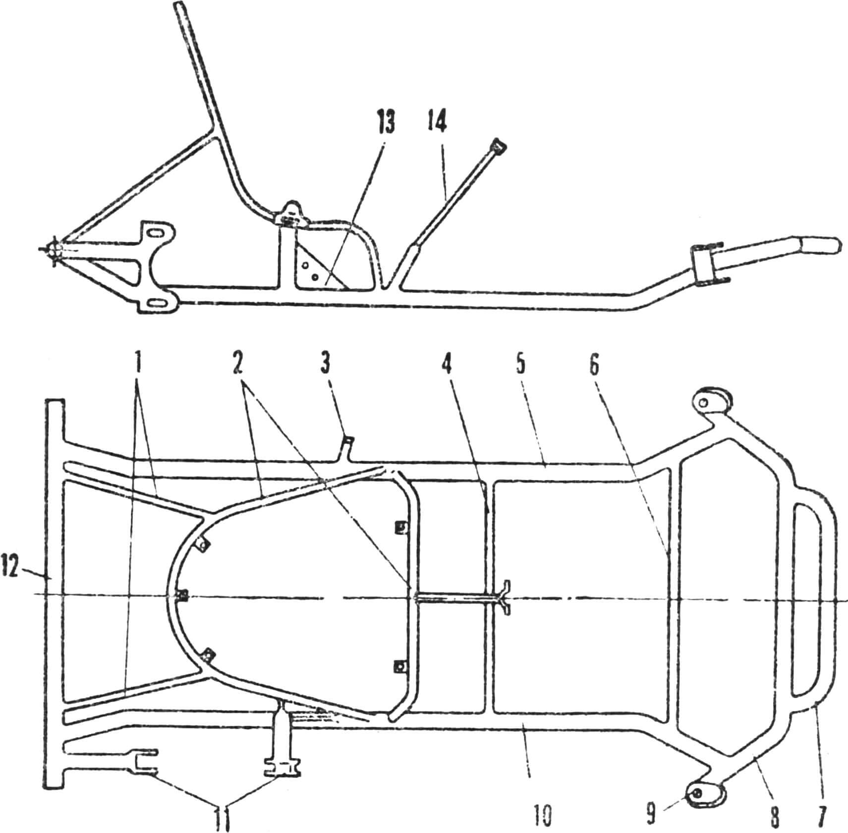
1 — seat frame supports (tube Ø 12 mm); 2 — seat frame (tube Ø 16 mm); 3 — brake cable stop (nut M8X1); 4 — middle frame crossmember (tube Ø 16 mm); 5 — left side member (tube Ø 25 mm); 6 — front frame crossmember (tube Ø 16 mm); 7 — protective arch — bumper (tube Ø 25 mm); 8 — front axle beam (tube Ø 25 mm); 9 — front axle lug (δ = 4 mm); 10 — right side member (tube Ø 25 mm); 11 — engine mounting brackets (δ = 2 mm); 12 — rear axle tube (tube Ø 25 mm); 13 — stiffness gusset (δ = 2 mm); 14 — steering column stop (tube Ø 16 mm).
On a level floor in the workshop, the track and wheelbase of the kart are marked. According to the marking, the front and rear axles are installed and the wheelbase is carefully checked again. After that, the length of the pre-bent side members (see Fig. 7) is adjusted and they are tack-welded to the axles. The remaining frame elements are fitted in place.
The seat is made from an aluminum sheet 1.5 mm thick, which is cut along the contour of the frame tubes that form the seat stiffness frame. The sheet is fastened to the frame with screws at five points, a 20 mm thick foam sheet is glued to it, which is covered with leatherette on top (glue 88).
On some of our class E kart models, so-called anatomical seats made of fiberglass based on epoxy resins are currently installed (see No. 7, 1968).
A 2-liter fuel tank is welded from sheet iron 1 mm thick. Along the mating surface with the seat, it repeats the shape of the backrest. A drain hole must be made in the tank lid to communicate with the atmosphere, and a motorcycle-type tap must be installed at the bottom. Fuel from the tank is supplied to the carburetor by gravity. The pedal levers (see Fig. 1) are made from tubes Ø 10 mm, platforms are welded to their ends, on which ribbed rubber is glued. The height of the brake and clutch pedals is 180 mm, the throttle pedal is 150 mm. The drives from the pedals are carried out by flexible motorcycle-type cables equipped with length adjustment devices.
The gear shift lever is located in the most convenient place under the steering wheel. The lever is connected to the engine by a rigid rod 6, made from a tube Ø 10 mm.
The kart uses a “Jawa-50” engine from the “Jawa 50/555” motorcycle with a displacement of 49.8 cm3, developing 2.2 hp at 5500 rpm, with a three-speed gearbox. But any other equivalent displacement can be used, for example Sh-51 or “Stadion S-22”. In this case, only the engine mounting design to the frame needs to be changed.
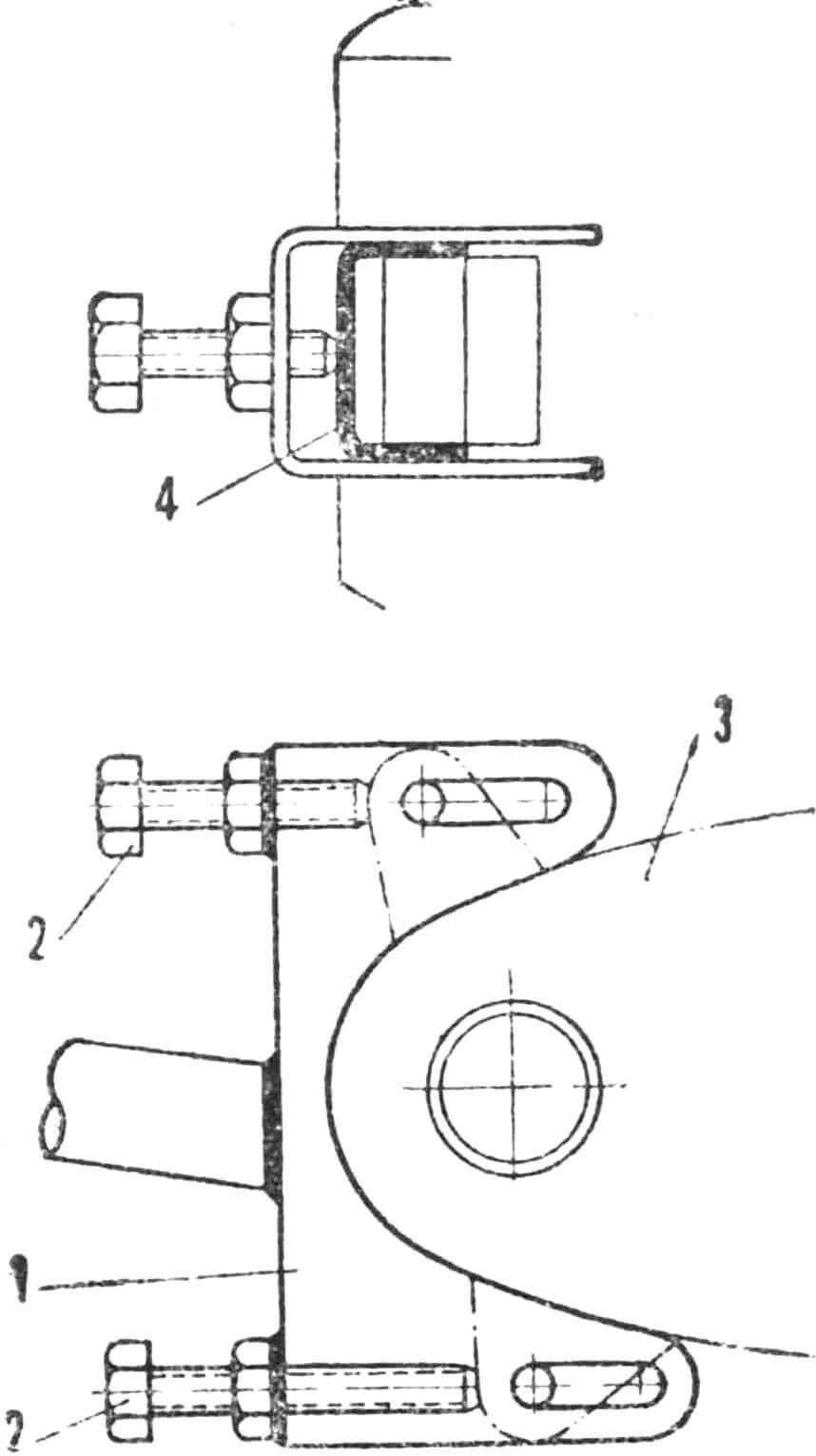
1 — engine mounting bracket; 2 — engine displacement bolts; 3 — “Jawa-50” engine; 4 — protective bracket.
A device that shifts the engine forward is provided for chain tensioning (Fig. 8). Two M8 nuts are welded to the engine mounting bracket 1, through which the engine is shifted forward with two bolts. A bracket 4 is provided to prevent destruction of the engine crankcase by bolts.
After testing and eliminating defects, the machine is disassembled, cleaned and painted with bright-colored automotive enamels separately for the frame and other parts.
KART TECHNICAL SPECIFICATIONS
Engine displacement … 49.8 cm3
Three-speed gearbox
Rear wheel tires … 265×85
Front wheel tires … 255×110
Wheelbase … 1020 mm
Track … 740 mm
Ground clearance 40 mm
Weight in fueled condition … 38 kg
Fuel tank capacity … 2 l
AC generator ignition
M. TODOROV, O. SHAEV Kursk
Recommend to read
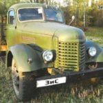 The FIRST post-war TRUCK ZIS-150 and ZIL-164
For many of my peers postwar truck ZIS-150 are associated with the period when in Moscow and other cities turned to mass construction of the famous five-story Khrushchev. Thousands of...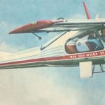 IVOLGA — air taxi
The Wilga is Polish "Ivolga". Indeed, this iisna white-winged machine with widely spread wings and forward, powerful paws-chassis resembles a bird, aimed ia a rapid breakthrough. A...
