Almost all bicycle drive designs share a common drawback that reduces their efficiency. This drawback is the uneconomical expenditure of muscular energy when shifting effort from one leg to the other as the pedals pass through the “dead points” (vertical position of the cranks). Most of the muscular effort at that moment is directed toward the pedal rotation axis and does less useful work than it increases wear on the bottom bracket bearings. It is no coincidence that cyclists move the cranks out of the vertical position before starting to ride. As a result, the power stroke begins with a partial loss of muscular energy, which causes premature fatigue.
The proposed improvement to the bicycle drive eliminates this drawback, allowing touring cyclists to ride in an economical mode by using muscular energy rationally, expending it almost as in normal walking.
To do this, the drive design uses a device that interrupts the interaction of the cranks with the chainring, ensuring free and rapid passage of the cranks and pedals through the sectors near the “dead points” by means of inertia.
The general view of the bicycle drive with the inertial interrupting device is shown in Figure 1, where the cranks 1 (with pedals) mounted on the bottom bracket axle 2 have a movable (sliding) connection with the chainring 3 via the interaction of pins on the hub 4, fixed to the right crank, and radial slots on the chainring 3. The slots allow the cranks to pass quickly through the inefficient zone, and the spiral bend spring 5 softens the impact at the end of their free travel.
As can be seen from the drive drawing, only the connection of the chainring to the right crank is modified, so such a drive can be made for any bicycle model.
For this purpose, a hub with protrusions is made from steel 30KhGSA according to drawing item 4, which is welded to the crank removed from the bottom bracket axle and modified in accordance with drawing item 1. The chainring is also modified — slots for the hub protrusions are made in it. The spring is made “cold” from carbon steel wire 4–5 mm in diameter and has one incomplete turn. The spring ends can be bent at home after heating the bend area over a gas burner. Guide washer 10 is made according to the drawing from any steel.
When installing the chainring, the pins of hub 4 are inserted into its slots, and washer 10 is fastened with three M4 screws. Limiter 6, made of soft wire and fixed to the chainring by bending its ends around its spoke bridges, prevents the spring from moving away from the chainring plane when it is under tension during operation. Then the right crank 1 with the chainring is secured in the usual way on axle 2 of the bicycle bottom bracket using wedge 9. When installing the spring, one of its ends is placed in a suitable hole on the chainring, and the other bent end wraps around the crank near the pedal.
To extend the adjustment of spring 5 force, a row of holes is additionally drilled on the chainring to the wire diameter for installing the bent end of the spring.
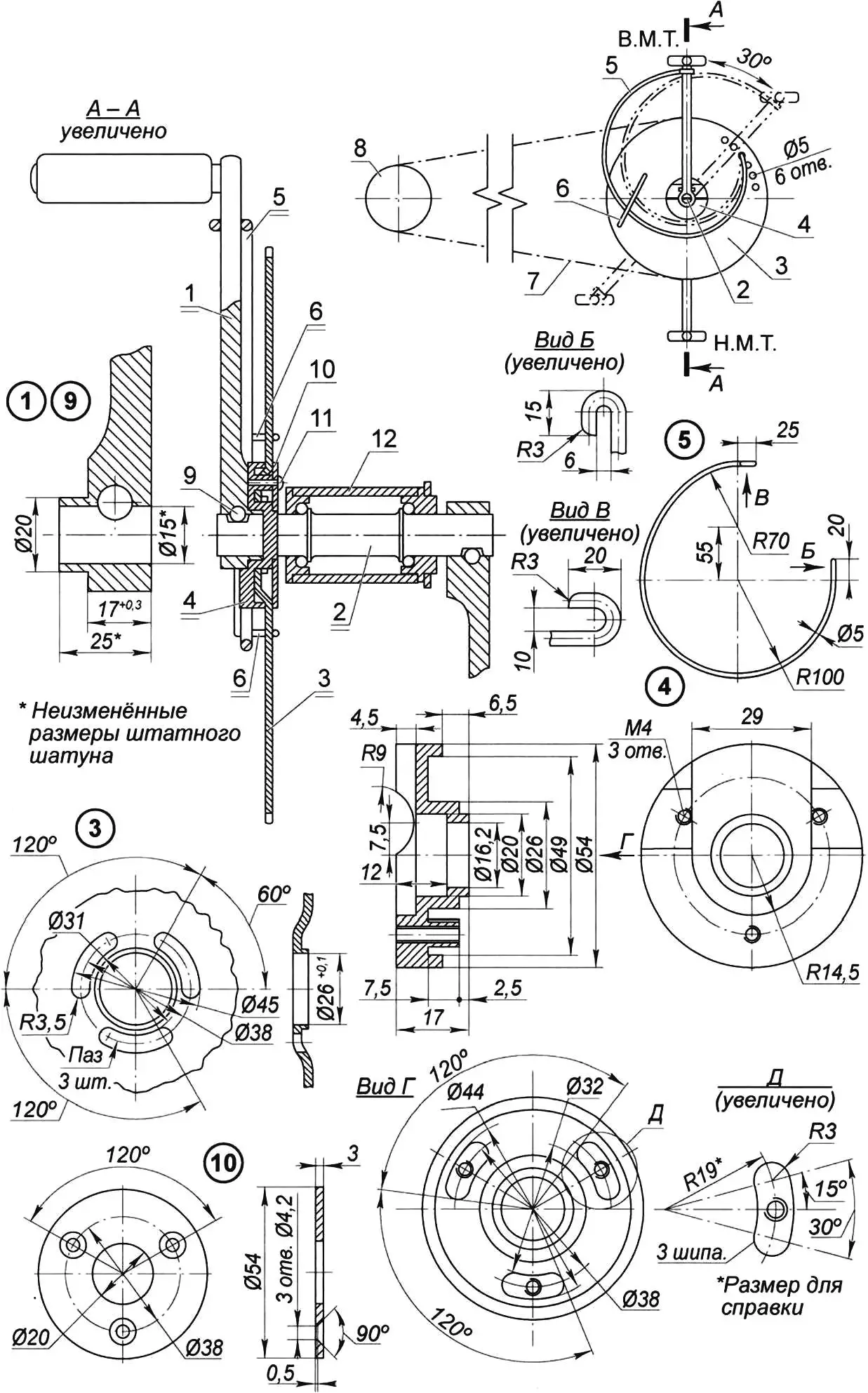
1 — modified right crank with pedal; 2 — bottom bracket axle; 3 — modified chainring; 4 — hub (steel 30KhGSA, round 55); 5 — torsion spring (carbon wire Ø5); 6 — spring limiter (soft wire Ø4); 7 — drive chain; 8 — driven sprocket; 9 — crank fixing wedge; 10 — guide washer (steel, sheet s3); 11 — washer-to-hub fastening (M4 screw, 3 pcs.); 12 — bottom bracket assembly
The drive operates as follows. In the initial phase, for example when placing the right foot on the right pedal in the top position, the cranks 1 together with axle 2 and hub 4 rotate until the hub pin engages the chainring 3, the spring 5 compresses and creates torque on the chainring. After applying muscular effort to the right pedal, the chainring is set in rotation — and the bicycle accelerates. As the right pedal approaches the bottom position, the working interaction of the cranks (hub pin) with the chainring is interrupted by delaying crank rotation relative to the chainring after reducing pedal pressure, due to the spring’s reaction and the bicycle’s inertial motion. The spring maintains chainring rotation and moves it away from engagement with the cranks. As a result, at the start of the next working cycle the cranks pass through the vertical region with some reverse angular offset relative to the chainring, ensuring free passage through the vertical and renewed spring loading for the left crank. The drive cycle then repeats.
Free passage of the pedals through the top and bottom positions eliminates muscular energy loss when switching work cycles, which increases drive efficiency. In steady operation, crank rotation is delayed and then they effectively push the chainring. Pedaling thus takes place in an economical “pushing” mode. This mode allows maintaining high speed without excessive effort and for a long time, similar to maintaining flywheel rotation with intermittent tangential force. The delay in crank rotation helps compensate for inertial forces on the cyclist’s legs in the “dead point” region during rapid rotational motion.
The economy and stability of the drive depend on the spring preload, which is chosen according to the rider’s weight and fitness. If after the power stroke the cranks do not disengage from the chainring — a stiffer spring should be fitted. Conversely, if noticeable muscular effort is needed for the pedal to pass freely through the top position and there is no working engagement of the cranks with the chainring during the power stroke — spring stiffness should be reduced, e.g. by choosing a smaller spring wire diameter.
For normal drive operation, the amount of reverse crank motion must be less than their initial angular offset. Under these conditions, the initial torque on the chainring is maintained during transients, which further enhances the spring’s damping for smoothing peak loads during pushing rotation of the chainring.
When getting used to riding a bicycle with this drive, the rider must pay some attention to keeping chainring rotation even with free crank travel. With practice, chainring rotation uniformity and the amount of reverse crank motion are maintained automatically and do not cause difficulty or discomfort.
Experimental road tests over about 3500 km confirmed the drive’s economy and reliability. Compared with a conventional bicycle, fatigue on long rides is noticeably reduced, which expands the cyclist’s capabilities.
Perhaps spring-loaded pedals relative to the chainring may also find a place in competitive sport, as has spring-loading of the rear part of the blade relative to the heel in speed skates.
«Modelist-Konstruktor» No. 2’2009, V. Zelenov
Recommend to read
 CHAIR SHIFTER
The limited size of the living area in the typical buildings awakened interest in versatile pieces of furniture. Cabinet from the wall, it became possible to extract the Desk or bed,... LENS FOR… MOBILE PHONE OR POCKET KVN
In the early XIX century the French scientist Augustin Jean Fresnel has created an unusual lens, which are not brushed solid piece of glass with a spherical surface, and a set of...
