THE LOG SPLITTER OF MY DREAMS

LOG SPLITTER OF MY DREAMSIn the well-known encyclopedia even the last century “Industry and technology” in volume on “the treatment of fibrous substances”, which is a tree, it is said that “in the works for the division of the tree matters … splitting”. And further: “wedge-shaped tool extends the shared part of the tree; here the cleavage of the tree at a distance greater than the tool can penetrate”.

 
Has an extraordinary number of types of axes. But to crack the most suitable mallet. It is not only in its greater weight, longer handle for a swing. Important – in the sharper the blade, sharpening. Scientists have found that the optimal value of its sharpening 40° -60°. In this case, the working side surface of the blade, helping to divide the block directed tensile forces in different directions, rasleela…..
 
The principle of operation of a mechanical cleaver is no different from the “manual splitting”. But here, the blade must fit the block exactly parallel to its longitudinal fibers, or the axe just stuck there in the tree. It is therefore necessary to provide a solid, first of all, the frame of the mechanism by which the movement of its main parts.
 
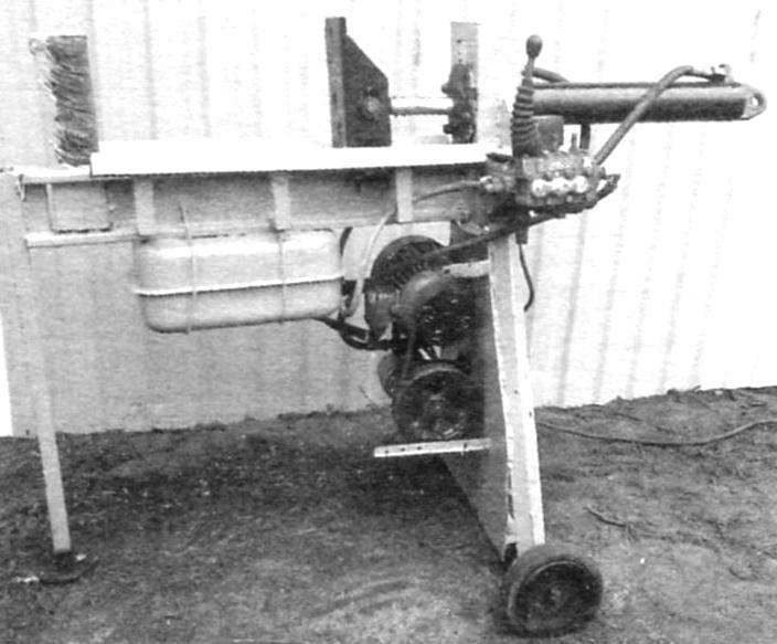
And because the quality of the bed stationary rail of the log splitter picked a relatively strong I-beam № 18U sizes 90x90x10 mm. on one side is the knife-the cleaver – pusher acting on the power cylinder with the pump and motor. I would like, moreover, that the mechanism can be moved from place to place. To do this, it needs to have wheels on the front and rear uprights.
Along the traverse cylinder moves the block towards the knife-cleaver. This item made of steel bar (steel 45) dimensions mm 400x80x50 and imprisoned on the sandpaper under 60° at the tip. At one end of the frame-I-beam – at its top, made the cut, inserted vertically cleaver and securely welded to both flanges.
 
At the other end of the frame welded the front cylinder. Its made out of steel channel sizes 180x70x9 mm height 400 mm. On the inner side of cylinder mounts already welded on the circular flange with four bolt holes with a diameter of 14 mm. At its centre is an opening for passage of the cylinder rod with a diameter of 60 mm.
 
DIAGRAM OF THE LOG SPLITTER
 
DIAGRAM OF THE LOG SPLITTER:
 
1 – knife; 2 – pusher; 3 – rod hydraulic cylinder; 4 – cylinder (channel 180x70x9); 5 – power hydraulic cylinder, stroke 600 mm (Ø90); 6 – flange; 7 – dispenser control; 8 – guide angles (50×50); 9 – electric motor 3.5 kW; 10 – the oil pump NSH-32; 11 – the front bearing; 12 – oil tank (20 l); 13 – t bases (90х90х 10); 14 – holder guide (150x40x5); 15 – back support

 
Pusher. The connection to the rod of the hydraulic cylinder, the rod diameter 50 mm
 
Pusher. The connection to the rod of the hydraulic cylinder, the rod diameter 50 mm
 
The knife and pusher on the frame. On the sides of the bed set rails corners dimensions 50x50 mm
 
The knife and pusher on the frame. On the sides of the bed set rails corners dimensions 50×50 mm
 
The pusher rod and the flange of the cylinder mounts to rear rack
 
The pusher rod and the flange of the cylinder mounts to rear rack
 
The pusher is made of steel sheet with a thickness of 10 mm. First cut the cost of size 150×300 mm and welded thereto two vertically notched rack dimensions 270×150 mm side cut. Drilled a hole with a diameter of 30 mm under the finger cylinder rod. Thus, the pusher can be connected with the power cylinder.
 
For the operation of the hydraulic cylinder picked up the motor 3.5 kW with 1500 Rev/min. As it turned out, the engine power in the work was enough. From it threw a belt pulley on the drive pump 12 – oil pump gear-dimensions mm. 146x159x137 Both placed on the edge of the cleaver under the counter cylinder. Oil tank capacity 20 l strengthened under the bed at its center.
To block fell down from the bed, along the sides at a distance of 90 mm had to stretch the guide parts of size 50×50 mm. They are mounted on three pairs bent at a right angle holders-shank sizes 40×5 mm, which is welded to the bottom shelf brands.
 
The control mechanism occurs through a dispenser R-80, MTZ. However, a few of the upgraded hide with his balls, locking lever for security purposes.
 
Pusher
 
Pusher
 
Front cylinder
 
Strut cylinder
 
Channel rear rack, 180х70х9 mm hose to the oil pump to the hydraulic cylinder
 
Channel rear rack, 180х70х9 mm hose to the oil pump to the hydraulic cylinder
 
Build the right node of the log splitter. In the foreground dispenser control R-80, tractor MTZ
 
Assembly of the right node of the log splitter. In the foreground dispenser control R-80, MTZ
 
The motor and the oil pump 32 is connected to belt pulley
 
The motor and the oil pump NSH-32 connected by a belt pulley
 
Now, if the lever is let go, it returns to its original position.
 
The stroke of the hydraulic cylinder is 600 mm, so the chump on the bed you can put a length of 40 – 50 cm, They are split into two parts, but can be chetyrehlistnyj knife.
 
Front support and back – on wheels – made of pipes with a diameter of 50 mm. They are also welded to the shelves brand.
 
The log splitter of this design working on firewood for the house for four years without interruption. There was no damage, and break it especially nothing.
 
R. VLASOV, Belarus

Recommend to read

  • FORGET ABOUT THE BATTERYFORGET ABOUT THE BATTERY
    Brand motorcycles "IZH" and "Java" can be fairly easily translated into bezakkumulyatornyh the ignition. I did it seven years ago, and so far — no complaints. What do you need? If the...
  • RADIO MICRADIO MIC
    We are talking about miniature and low-power VHF transmitter that operates at a distance of only a few tens of meters. The contractor, using a wireless microphone, can move freely around...