Another tube is needed for the long end of the rocker arm. Its length is about 2 m, and fixed it exactly the same as the previous knee.
In a simulator there is another hinge joint, which connects the rocker and glider design it is quite simple, but it will take a lathe and welder.
And now to the most interesting part of the work – production layout of the airframe. Prepare pine bruski section 25×25 mm – of them going to the farm of the fuselage, some parts of the tail and the front edges of the wings and ailerons. You will need and the Reiki section 10×25 mm for the rear edges of the ailerons and of the tail framework. All sizes of sections and lengths of the blanks indicated on the drawings.
Simulator – simulator of flight of a glider:
1 – gravel, quarry stone, cement mortar; 2 – vertical strut (steel pipe); 3 – duck to lay a safety line; 4 – the plug hinge; 5 – safety lanyard; 6 – rocker “pie” (welded steel pipes); 7 – barrel-counterweight; 8 – filler-counterweight (gravel or sand); 9 – ball bearing vertical hinge; 10 – layout of the airframe; 11 – universal joint suspension layout; 12 – horizontal hinge
Wing. It is based dvukhpolosnykh spar, consisting of two five-meter rails section 25×50 mm. If you fail to find such long rods, crescite their two shorter docked “on a mustache” with epoxy glue (the length of the joint should be not less than 150 mm). For the trailing edge will need a five-meter rail section 20×70 mm. Note that all the strips should be straight grained, without knots and ROE.
Rib. Wing need for their twelve – six on each half-wing. The best material for rib – plates with a thickness of about 10 mm and a width of 120 mm. Suitable pyatisantimetrovym plywood. In accordance with our drawing mark one of the blanks and carefully apply her contour. Then, using it as a template raschertite eleven others. After cutting out blanks pull them out studs in the package and process together using a plane, rasp and sandpaper. Then cut the grooves for the spars and the front edge of the wing.
Assemble the wing better on the smooth area of the field. Spread a sheet of paper and in accordance with the drawing will watertite planned projection of the wing with the exact location of the ribs, spar, winglet and leading edge. After that, two or three small nails attach the drawing the bottom shelf of the spar on it – all the twelve ribs. For fixing them on the spars need epoxy putty of mixed epoxy glue sawdust. In the same way -with the help of epoxy ligament – joined ribs from the top shelf of the spar.
To secure the front and rear edges, cut them twelve grooves under the tail and toe of the ribs and fluff the joints with an epoxy adhesive, set in place, temporarily primatv edge to the spar with twine. After polymerization of the adhesive strip the frame so that there were no irregularities and protrusions. The wing is ready.
Ailerons. For a start it is necessary to draw on a sheet of paper plazovy drawing as you did when assembling the wing. Similarly, clamp temporarily at the Plaza in the front and back edges, and then adjust the diagonal and transverse frame rails. Attach the frame elements is easiest with epoxy ligaments and small studs.
The docking wing and ailerons it is best to postpone the final Assembly, and now need to assemble the base of the cockpit. This will require slats 25×60 mm cross-section, and a sheet of plywood chetyrehkilometrovoy size 400×850 mm. First dock rail with the wing, insert them between the shelves of the spar and clamp on the trailing edge with epoxy glue, ligaments and nails. Next, cut out the crossmember, secure them and at the same time install a floor made of plywood sheet.
The Assembly of the fuselage beams begins with a careful marking of each of the workpieces.
We advise you to sort of stocks. Using wooden sticks secure all three fuselage longeron on the floor so that their relative positions correspond to the drawing. Then mark on the rail where they dock with the braces, and then place cut the rail-braces and secure using epoxy ligaments. The rudder and elevators are set up exactly the same as the ailerons.
The Assembly machine begins with the docking block of the cabin and wing with fuselage I-beam. Note that all connections must be solid and reliable. So join items necessary for epoxy adhesive, increasing the nodes of the dural lining. Make them from a sheet thickness of 1.5-2 mm. For that of thick paper or thin cardboard first, cut the template to fit with scissors to the junction, and then it is itself a decorative metal overlay. Mounting plates – steel bolts with thread M5 nuts.
In the design of our glider can count a considerable number of metal nodes are the elements of the control system and loop attachment of rudders and ailerons, and docking. Almost all of them can be made of sheet duralumin with a thickness of two to four millimeters.
Control system. Its main bodies are the pedals and handles. The easiest way arranged foot control pedals, which is duplici the lever, the cables connect to the control horns of the rudder.
Somewhat more difficult is the manual control. Handle the glider has two degrees of freedom – it can vary as the “right – left” and ” -“. Look carefully at the picture. Should reject the knob “on” – pull connected to it, turn duplici lever in the rear, and that will trend upwards the Elevator – car will go airborne. Accordingly, giving the pen away, you turn the glider into a dive – glider will lower the nose and begin to decline.
Moving the handle left / right arrow, you will activate a system of levers and rods by which the ailerons change their position relative to the wing. When the Aileron of the left wing is deflected up and the right Aileron goes down and the glider entered a left roll. The movement of the handle in the opposite direction will cause the right Bank.
I suggest you carefully examine the drawings, joints of elements of the management system. Most rods performs complex spatial motion, therefore, each of the joints must provide at least a few degrees of freedom. The most simple design, using pieces of rubber tubing with push-in metal bushings.
Themselves thrust connecting arm mounted on the Central tube of the control handle, with the control horns of the ailerons, bent steel rods with a diameter of 5-6 mm. On the bent ends of the rods threaded. The lever is fixed to the pivot arm using two nuts, two washers and lock nuts.
We now consider the rods that connect the control stick with the Elevator. They are made of duralumin tubes from the ski sticks. They are quite long lasting and, importantly, the lungs. As can be seen from the figure, one of the rods not directly connected to the control horns on the Elevator and goes to the distribution site, mounted on the tail of the glider and the two lower rods is connected with the right and left elevators.
Install control horn on Elevator or Aileron (19):
1 – hog; 2 – nut; 3 – the pin; 4 – wheel steering (Aileron or Elevator); 5 – drive rod; 6 – washer-emphasis
The design of the layout of the airframe:
1 – the side walls of the cab; 2 – stick control roll and pitch; 3 – the control pedal for the course; 4 – l-shaped rocking actuator Aileron; 5 – drive rod of the Aileron; 6 – shaft control knobs; 7 – cockpit; 8 – plywood paneling of the cabin; 9 – wing; 10 – wing Aileron; 11, 12 – pull the Elevator drive; 13 – a roller under a control cable rudder; 14 rocking of the Elevator drive; 15-diagonal rib; 16-power brace; 17-trailing edge Aileron; 18-rib Aileron; 19 – front edge of the Aileron; 20 – the horn of Aileron drive; 21 – rear edge of the wing; 22 – spar; 23 – front edge of the wing; 24 – rib wing; 25 – rod driven ailerons; 26 – diagonal rib; 27 – stabilizer; 28 – steering wheel-height; 29 – the lever of a drive of the ailerons; the 30 – hinge of the Aileron; 31 – area; 32 – area
After installation of the control system, set cabin light plywood seat or plastic seat from the map. Sit in it, place your feet on the pedal and think about whether it is convenient to control the glider. If the knees stick out too high, and the handle is too close or too far from the seat, the pedals have to move in accordance with your height.
Cording to the airframe. For her you will need a fabric such as percale, pillow tick or Mylar film. First glued to the frame with amelita or nitrocream with subsequent impregnation with nitrocellulose lacquer and painted by nitropaints. Mylar film glued with glue type BF-2 or “Time”, after which the stretched hot -need to iron the lining hot iron. To paint Mylar should not be.
The glider rocker is mounted on a “crane” using a ball joint, providing the machine the ability to rotate about a vertical axis and also move in roll and pitch. At the opposite end of the rocker is fixed 200-liter barrel-counterweight filled with gravel. It is desirable to mount the barrel so that it was possible to move it through the pipe. This will give the opportunity to balance the simulator for any pilot weight.
“Flights” are made only with insurance – for this to both ends of the rocker arms are tied strong nylon ropes that hold the two hands of the belayer.
“Flight” is best done with a smooth, steady wind – its speed should be about 10 m/s the First stage of training – the usual “balancing” on the ground – you have to learn to fend off any roll, and only after mastering this skill you should go to “UPS” and “landing”. When “off” try not too hard to lift up the nose of the glider, otherwise you can fall into a kind of tailspin. Don’t try too sharply to translate the glider into a dive – in this case you can not manage to align the glider near the ground.
In any case at sharp evolutions of the airframe, which would only lead to trouble for the pilot, insuring with the help of ropes must hold the yoke. After landing, the pilot remains in a glider as long as the belayer will not clip securely to the glider on the ground. At the end of “flight,” the rocker should be fixed by nylon ends in a horizontal position. Otherwise, with a strong gusty wind trainer may simply collapse.
I. EVSTRATOV, engineer
Recommend to read AN OTTOMAN WITH A SECRET Good to have in the hallway a small chair or Ottoman for pereobuvaniya. If you don't, I suggest to use this kind of hint. Take any wooden box (even mail order) and simple Refine it:... A WHITE SAIL… A white sail gleams In the mist of the blue sea... These lines from a beautiful poem by the great Russian poet always evoke a dreamy sadness and a burning desire to go into the... 
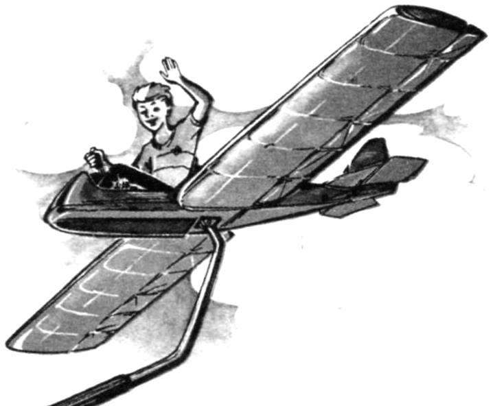 …Control knob soft is selected, the glider can easily lift the nose off the ground and shoots up. There, on a five-meter altitude, where popiskivaet on planes fresh wind, we are now going to demonstrate what they have learned to parry the roll of the glider, deviation from course, it’s a “press” machine to the ground, find the optimal angle kupirovaniya, which is necessary for a proper take-off… everything in this free flight! Meanwhile, our glider… can’t fly. Installed it on the building, resembling a well sweep. And is, in fact, the layout. To make such a trainer in the club or at the station of young technicians is not so difficult. It will allow children, dreaming of the sky, to practice a lot of exercises necessary for mastering flying skills.