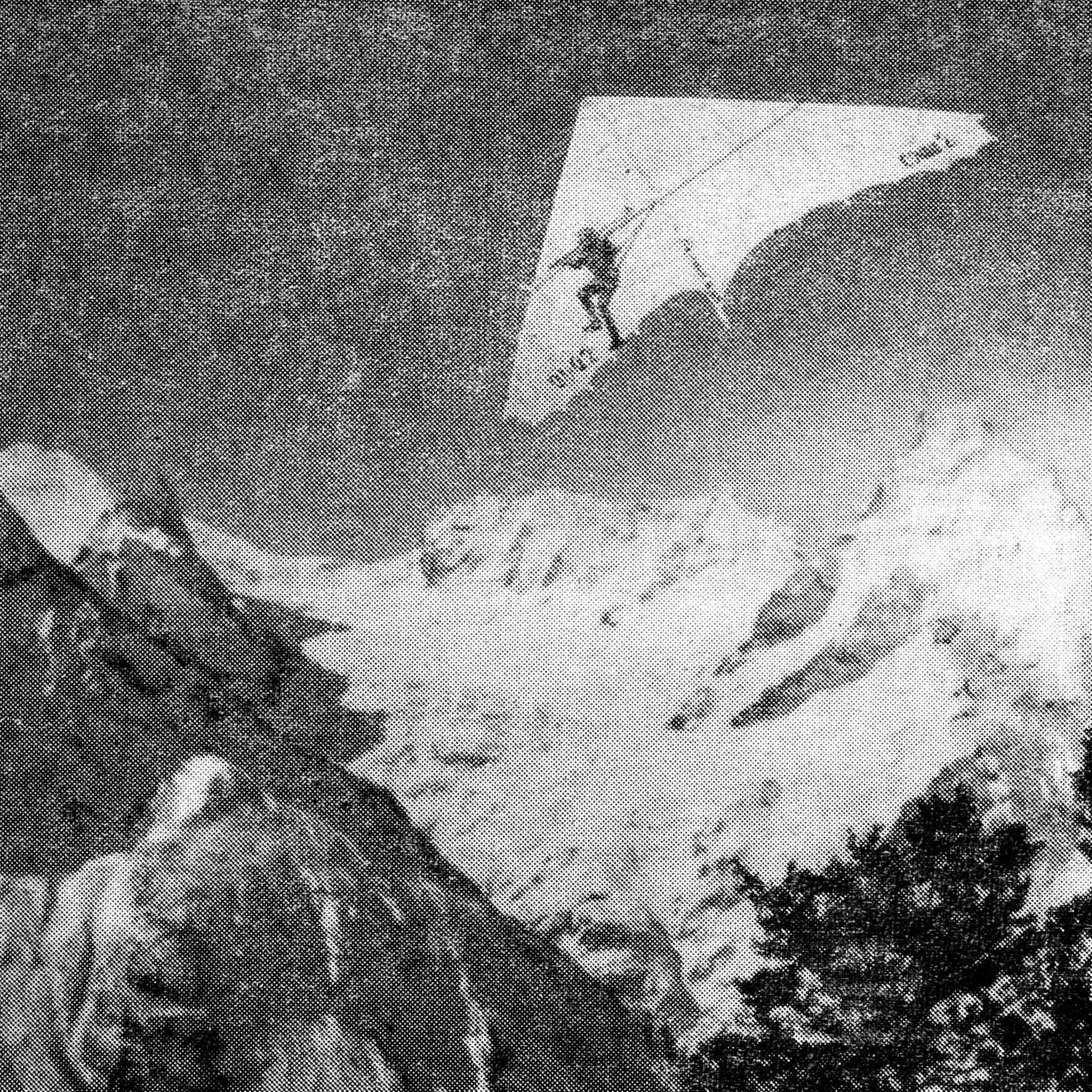
The best delta glider of amateur construction that took part in the «Dombai Peaks» competition in 1978 was recognized as the «Sokol-2». Its creator was V. D. Mikhailov, a Master of Sport from Leningrad, a well-known specialist in designing and sewing yacht sails. Therefore, his desire to use the latest achievements in sailing sports when designing the delta glider is quite understandable. As a result, in terms of the quality of the canopy, «Sokol-2» had no equal among the machines flying over the Caucasian peaks.
During his very first flight by V. D. Mikhailov—from Yusa to the «Russian Glade» (height difference of about 800 m)—the knowledgeable spectators noted an exceptionally correct airfoil profiling and a high degree of purity of the shape of his machine.
So what are the features of this delta glider? In its frame design it differs little from the traditional one (Fig. 1). Only two things can be considered essential: the bending of the front part of the keel tube, forming a 130 mm-high bracket to give the most advantageous profile to the central part of the canopy, and the attachment of the cables—stays of the side tubes—which provides them with the required flexibility. A flexible structure is, to some extent, capable of self-regulation—for example, elastic damping of unexpected wind gusts.
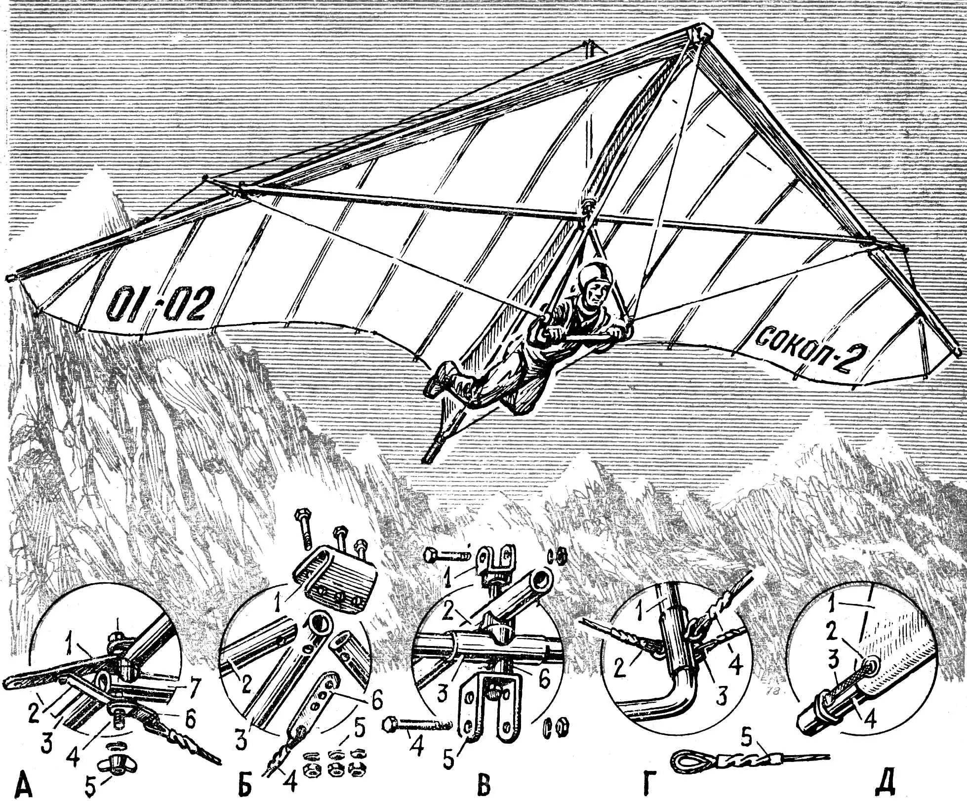
A — node connecting the transverse and side tubes: 1 — craspitsa, 2 — craspitsa strut, 3 — side tube, 4 — M8 bolt, 5 — M8 wing nut, 6 — eye of the transverse tie-down cable, 7 — transverse tube; B — front node for mounting the keel and side tubes of the frame: 1 — sleeve clamp, 2 — side tube, 3 — keel tube, 4 — stay cable, 5 — M8 nuts, 6 — stay-cable bar; C — central node: 1 — mast base, 2 — keel tube, 3 — coupling of the transverse tube, 4 — M8 bolt (attachment of the steering trapezoid), 5 — bracket of the steering trapezoid, 6 — shaped washers; G — node for attaching the cables to the steering trapezoid: 1 — trapezoid, 2 — rear cable, 3 — side cable, 4 — front cable, 5 — termination of the cable end on a thimble (with twisting into a copper tube); D — attachment of the keel part of the canopy: 1 — keel, 2 — grommet, 3 — lavsan tape or cord, 4 — keel tube.
It is still difficult today to say how correct V. D. Mikhailov’s assumptions were; however, let us remember that a bird’s wing is also very flexible and elastic in response to changes in the direction and strength of the air flow. There is no doubt about one thing: to ensure progress in any matter—and especially in such a new and little-studied field as delta gliding—search is required and, absolutely, flight experimentation. And the «Sokol-2» flew excellently, not only in the hands of its creator: other pilots who tried the delta glider also gave a good review of its flight characteristics.
During the scientific and technical conference held in Dombai, V. D. Mikhailov made a detailed report on the features of his machine, and in particular—the method of cutting and sewing the canopy. We briefly present this information and the delta glider «Sokol-2» drawings provided to the editorial office by the author.
Just as it was at the dawn of aviation, and as it is today at the dawn of delta gliding, almost every pilot is at the same time a designer and a manufacturer of his own machine. Even when some enthusiast begins to build a delta glider according to already tested drawings, he will inevitably introduce something of his own—either consciously or because of the lack of recommended materials. And if there is an opportunity to purchase everything required and manufacture all parts at a high technological level, it is simply impossible to resist making experiments.
Observing the behavior of the delta glider canopy in flight, I concluded that for most machines it fills with air not in the way needed to obtain maximum lift force (and ultimately, the magnitude of that lift determines the flight qualities of the machine). Many years of sailing sports gave me a precise knowledge of what shape a good sail should have so that it can provide maximum thrust in a given wind. And since, as the famous Russian pilot P. Nesterov put it, «in the air everywhere there is support»—the meaning of thrust for a sail is analogous to lift for a delta glider canopy. Therefore, the delta glider canopy should be cut and sewn similarly to the best types of sails (a suitable example is the «Bermudan gaff sail»). The canopy should be made in the form of two such sails, stitched together by their bases (lower leech edges). Any required curve (for example, an S-shaped profile) can be laid into this central seam. With the help of the keel pocket, it will always preserve its shape in flight—i.e., in other words, maintain the most advantageous aerodynamic profile. And the sewing technology (see Fig. 4) will preserve this most advantageous profile all the way to the end of each wing (console), giving the possibility to change it somewhat to obtain the so-called «washout» (twist).
The seam construction is given for calendered lavsan (Dacron).
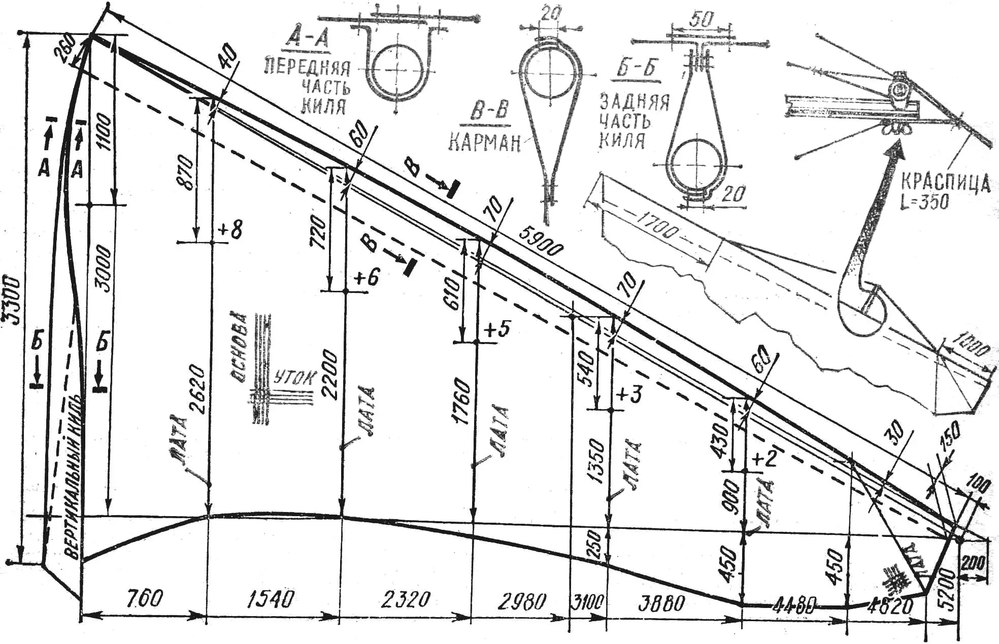
The sail is made starting with drawing, to full scale, the view in plan shown in Fig. 2 on a flat floor or asphalt pad, marking all the main lines as well as the seam lines connecting the panels. Of course, their layout must correspond to the width of the available material. After that, by laying the material onto the drawing, it is cut into pieces of the required length—from the centerline toward the ends of the wing consoles. For saving material, after cutting the first piece, the roll can be turned so that the second piece lies exactly along the line of the side tube. After cutting the required number of pieces (it may be different depending on the material width) and laying them out on the drawing, the overlap of the seams is marked with a soft graphite pencil or a marker in accordance with the scheme shown in Fig. 2. The edge of the upper panel is trimmed along the profile line (shown with a digit with a plus sign), while the edge of the lower panel is straight.
Experienced sailmakers sew calendered lavsan without preliminary tacking or gluing—immediately feeding the material into the machine and guiding it under the presser foot according to the pencil markings. For beginners this does not work out right away; therefore, there is no reason to rush and be upset by failures. It is convenient to do this work with two people.
There are two ways to join the panels: first by pairs, then sew two pairs, and so on. The second method is to stitch continuously, from the wing tip toward the root, with the seam shifted to the outside of the machine (in this case, only one panel will always be under the machine yoke).
The described sail-sewing technology makes it possible to obtain a sail whose required profile is given in advance. In this case, there is no need for all kinds of additional tensioning means (rubber tie-downs attached to the mast, etc.).
The first flights confirmed the correctness of my calculations. After the very minimal run, the canopy filled with air, acquired elasticity, and pulled upward swiftly; in flight it was very stable and responded excellently to control. In addition, the described sail was completely noiseless in flight: it has no back-edge flapping, no sharp whistling, and so on.
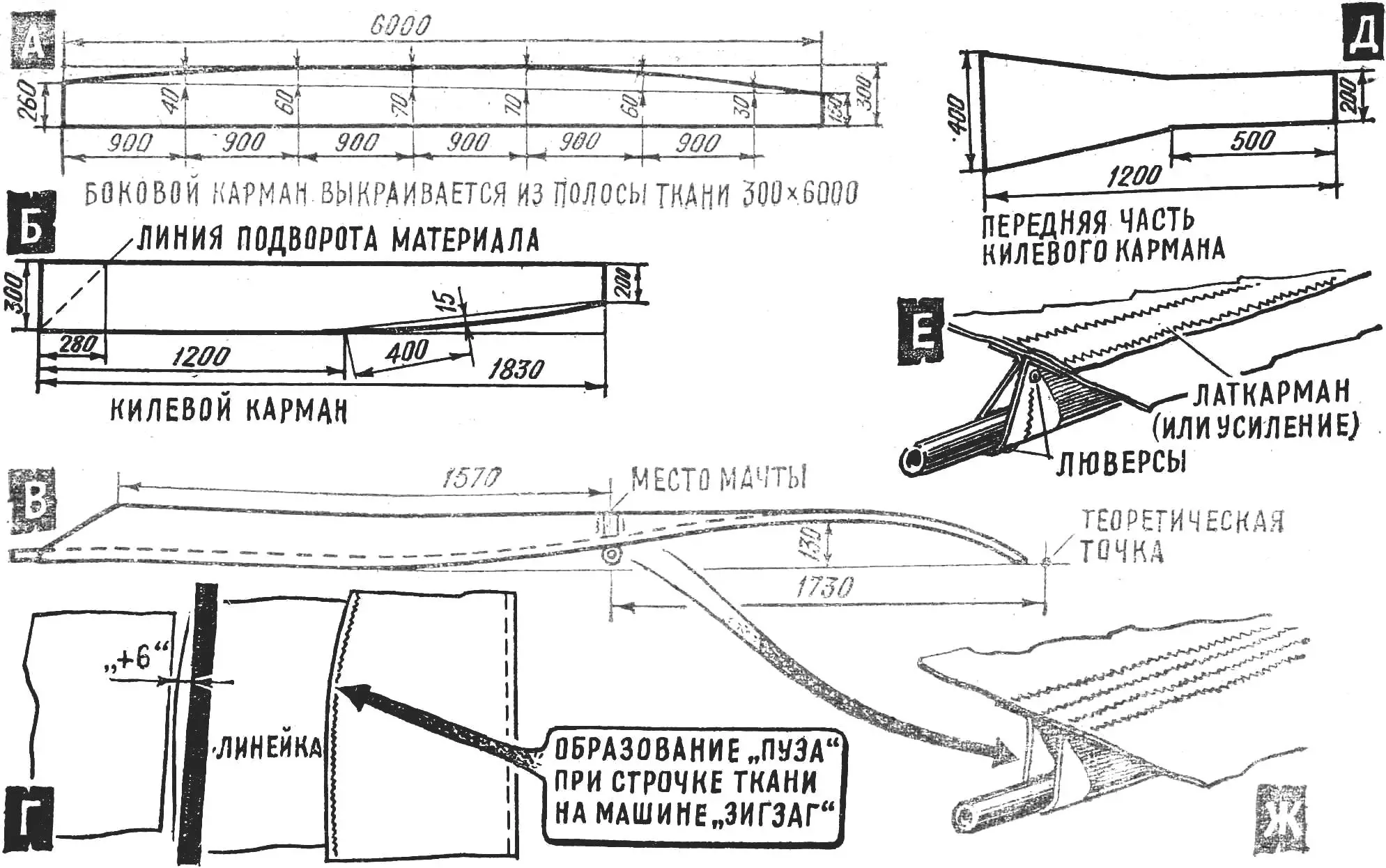
A — side pocket (each is stitched from two strips of fabric along the leech (pattern) line); B — keel pocket (rear part); C — keel pocket (side view projection); G — formation of the «belly»: the edge of the upper panel that has the curved (pattern) line is sewn to the lower panel that has a straight cut; the curvature of the upper panel is determined with a flexible ruler and the numbers shown in Fig. 2 with a plus sign; D — front part of the keel pocket, cut along the base (warp thread); E — position of the keel pocket on the central tube (rear view); J — position of the front pocket on the central tube.
I think that following this path it is possible to create even more aerodynamically advanced delta gliders, without changing the frame construction—just varying the angle at its tip somewhat. Everything else can be achieved by improving the sail quality, about whose possibilities we still know very little!
The article «Sokol-2» — conqueror of Dombai was already in the issue when it became known about the unprecedented group flight of Leningrad delta gliding enthusiasts from Elbrus. Five brave men—Mikhail Kotelnikov, Oleg Boldyrev, Alexander Amburkin, and Vladimir Graf—under the guidance of Master of Sport Viktor Ovsjannikov finally realized their dream.
Ovsjannikov’s first attempt to conquer Elbrus was made the year before. Unfavorable weather conditions thwarted his plan: reaching the summit turned out to be impossible, and Viktor made his flight from the «Shelter of Eleven» platform, from an altitude of 3,850 m above sea level.
August 1978 arrived. Five delta glider pilots set out for the summit of Elbrus. In total, they spent three days raising their machines to an altitude of 5,200 m. Many different conquerors had seen the gray giant Elbrus in his day, but such people climbed his snow-covered dome for the first time. Besides the traditional backpack, each carried along a long bundle with the packed delta glider.
Near the very summit, the assembly began. The sun was shining brightly, and far below the Baksan Gorge and the surrounding mountains were clearly visible. Then came a short run-up from a small trampled patch in the snow, and the delta glider pilots rose over Elbrus one after another. After half an hour of flight, their winged machines landed in the valley. These were delta gliders of Vladimir Mikhailov’s design—similar to «Sokol-2», the description of which you have just met. In difficult conditions of high-altitude flight, they demonstrated their high qualities!
«M-K» 11’78, V. MIKHAILOV, Master of Sport of the USSR, Leningrad
Recommend to read
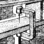 INSTEAD OF A HAMMER — CLAMP
Often there is a situation when you need to hammer a nail in a place where the hammer will not pull back, shelf, drawer, Cabinet. This sometimes resort to "detour" maneuver: - nail, he...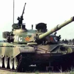 TANK “TYPE 98” ARMY OF CHINA
The Chinese tank "Type 98" is considered a model of armored vehicles of the third generation. The engineering of this started back in the 1970s, Then developed experimental tanks WZ-and...
