The upper longitudinal members from the first to the third frame (near the cockpit) — reinforced — cohesive of the two in height and glued bars. Even on the sides of the cab between the second and third frames on both sides of each bulkhead of the center section mounted racks, supported by struts. Stands as the third frame, fixed at an angle of 4° to the vertical — mounting angle of the wing.
The third frame serves as both a support for the seat back. At the same frame on top of the fortified security arc height 510 mm, made on the mandrel of percia pine sticks. Support the seat are the spars of the wing. In addition, the seat is reinforced own struts, spars and braces, fastened together with gussets (triangular inserts) epoxy resin.
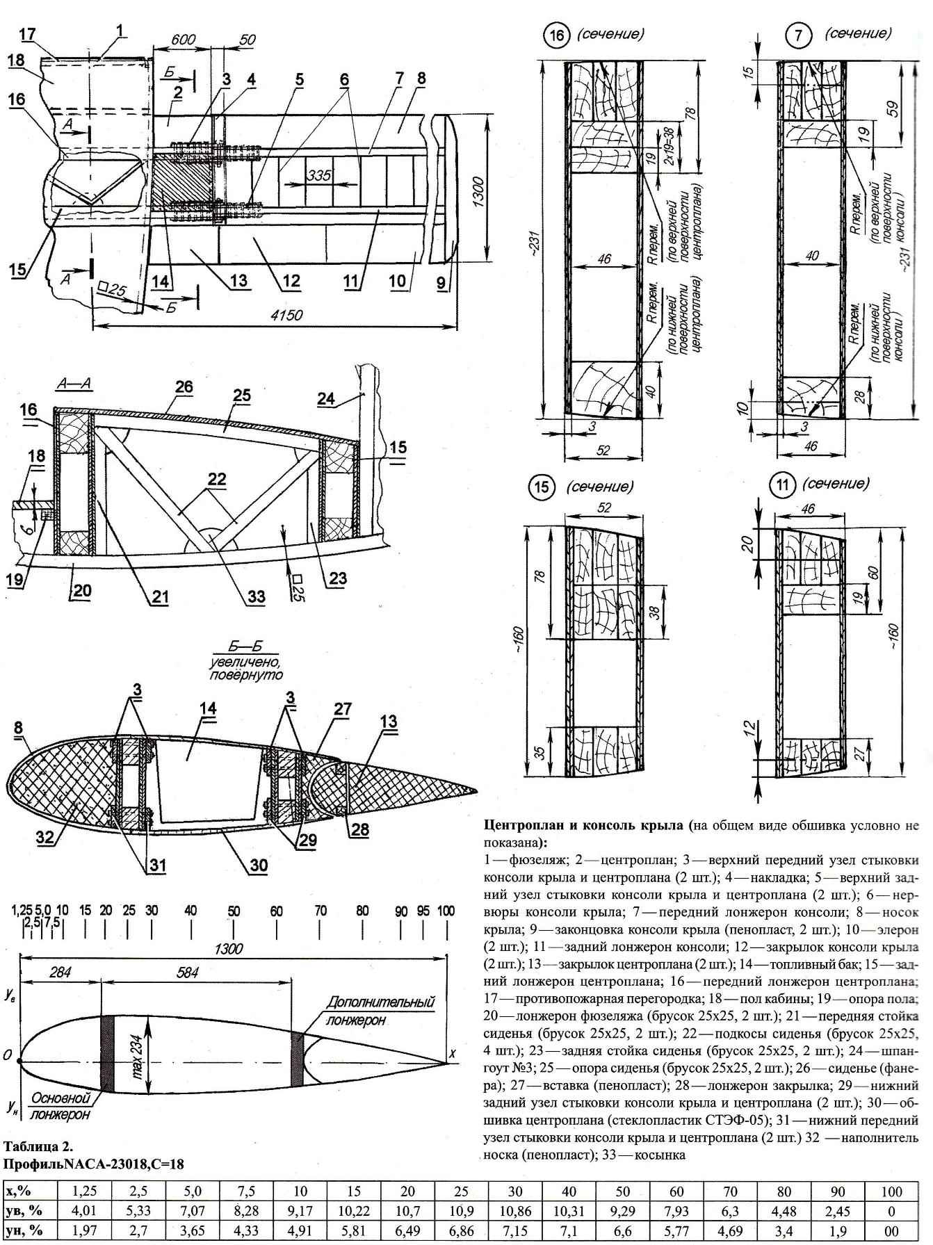
The center section of the wing and the console (in General, the sheathing is not shown):
1 fuselage; 2 wing; 3—upper front abutment wing and center section (2); 4—panel; 5—upper rear abutment wing and center section (2); 6 — rib wing; 7 — front longitudinal console; 8 — wing sock; 9—the tip of the wing (foam, 2); 10—Aileron (2); 11—rear spar console; 12—flap wing (2 PCs.); 13—the center-flap (2); 14—fuel tank 15—rear spar of the wing; 16 — front spar center section; 17—fire bulkhead; 18—cabin floor; 19—bearing floor; 20—the spar of the fuselage (bar 25×25, 2); 21 —front seat (brick 25×25, 2); 22—struts seats (bar 25×25, 4 pieces); 23—back front seat (bar 25×25, 2); 24 — frame №3; 25—support of the seat (the bar 25×25,2); 26—seat (plywood); 27 insert (foam); 28—longitudinal flaps; 29—lower rear abutment wing and center section (2); 30 — covering center section (fiberglass STEF-05); 31—front lower abutment wing and center section (2 pieces) 32 —filler sock (foam); 33—solitaire
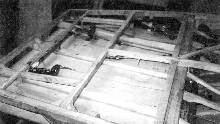
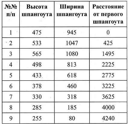 Only the fuselage has nine frames. The size of their framework and location along the length of the fuselage are given in table 1.
For forming the fairing of the fuselage on top of the fourth, fifth, sixth and seventh frames fitted handles 3 mm plywood shaped like the arc of safety, fastened together with stringers made of pine slats with a cross section of 10×10 mm.
Another shackle is mounted between the 3rd and 4th frames.
Fuselage is made ready for sheet plastic, glued to the frame member epoxy binder, with pre-sanding the mating edges to make them rough.
The hood consists of a bottom and top lids, laminated of fiberglass epoxy resin To-115 in foam matrices.
The wing has a profile, MAAA-23018, for which data are given in table 2.
 The wing is straight without the narrow, two-spar, technologically divided into the center section and the console. Front spar takes about 70% of the load, the second back — about 30%. Spars — box, their upper shelves — from perakee pine sticks, lower the main — out of the ordinary, subsidiary — also from parklea, walls from 3-mm plywood. Wingspan shelves spars consoles easier — inside is reduced in height.
Profilebase ribs are made of 3 mm plywood, light weight, round holes and reinforced from the front to the rear spar pine handles a cross section of 15×15 mm. wing Area is 10.8 m2 chord — 1300 mm. wing setting Angle and the same transverse V — +4°.
In the center section (between the spars) on both sides of the fuselage are two fuel tanks with a total capacity of 80 liters (40 liters each). Tanks are welded from steel sheet with a thickness of 1 mm and is connected with feed tank with a capacity of 1 liter rubber hoses with a diameter of 16 mm.
Toe wing is located at a distance of 284 mm from the first frame. The cavity between the ribs in the toe of the wing is filled with foam. For-ending wing and rear inserts — also the foam. The skin of the center section and consoles, fiberglass, and from the front to the rear spar is the same finished glass fiber sheet stamps STEF-05 that was used for the fuselage skin.
The hinge wing panels and center section made of steel plates 4 mm thick in the form of retaliatory eyes, fixed on upper and lower shelves of longerons in a manner that ensures the installation angle consoles relative to the center section +4°. The holes in the lugs under the connecting bolts reinforced with welded washers.
Stabilizer and Elevator:
1 —the main spar of the stabilizer; 2—auxiliary spar of the stabilizer; 3—filler sock of stabilizer (foam); 4—rib (plywood s, 10 PCs); 5—eyelet rudder pendants (3 pieces); 6—covering of the stabilizer (GRP); 7—ending of the stabilizer (2 PCs); 8—spar of the Elevator; 9—the toe of the Elevator; 10—blade rudder (foam, 2 PCs); 11 opposed; 12—casing of the Elevator (GRP); 13 —lug attachment of the Elevator to the stabilizer (3). 14—ending rudder (2); 15—pylon rudder; 16—the fuselage
 The ailerons and flaps on the same design — made from foam with a wooden P-th spars (shelves made of pine sticks and the walls of the 3 mm plywood) and covered with fiberglass.
Flaps — composite (centroplane and console). Connected by u-joints.
Includes horizontal tail stabilizer and Elevator. Stabilizer — cantilever, by design, it is the same as wing: dvuhkonturniy, with plywood ribs reinforced with pine battens (cross-section 10×10 mm). Sock — foam and covered with glass fiber epoxy resin in two layers. The ending is also foam covered. The stabilizer attached to the upper longerons and the last two frames of the fuselage, and connected to the rear (optional) the spar and bottom rib keel. On the rear spar of the stabilizer is hinged the Elevator, which on the longitudinal mounted three eyes.
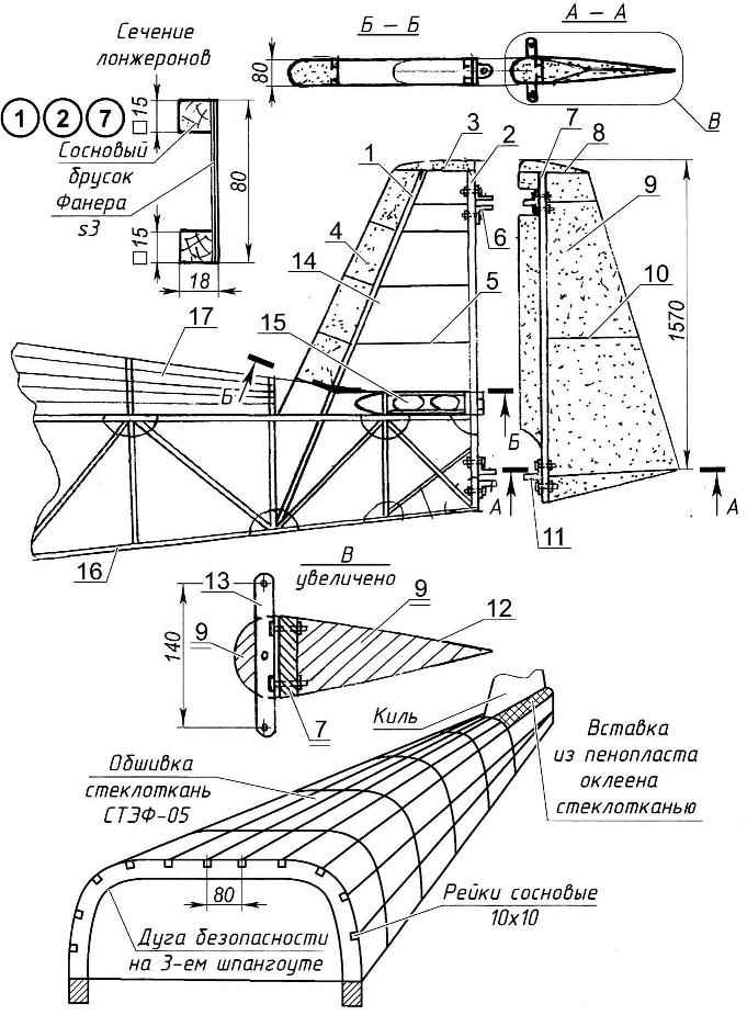
The tail of the plane:
1 —front (tray) longitudinal; 2—rear spar; 3—zakonov of Kiel; 4—filler sock of stabilizer (foam); 5 — rib keel (plywood s); 6—lug for attachment of the rudder (2); 7—spar of the rudder; 8 -fin tip (foam, covered with two layers of fiberglass in epoxy binder); 9—filler (foam); 10—rib (3 PCs); 11 —eyelet hinge the rudder to the keel (2); 12 — trim rudder (two layers of fiberglass in epoxy binder); 13—bellcrank of the rudder; 14 — sheathing of the keel (two layers of fiberglass in epoxy binder), conventionally not shown; 15—the stabilizer; 16—the frame of the fuselage; 17—frame fairing
 The Elevator is single-spar, the toe and shank of foam. Covered with glass fiber epoxy resin. It consists of two parts, United among themselves one spar. Spar is a box type. The lower and upper shelves — solid pine sticks and the walls are all from the same 3-mm plywood. Mounted on the longitudinal response of the lugs of the suspension to the stabilizer. Together with the middle lug mounted also the counterweight of the Elevator and hog steering. The weight of the counterweight — lead.
Vertical tail consists of fin and rudder. Keel — dvuhkonturniy, is associated with the fuselage structurally: its front spar passes through the frame and fastened to the lower bar of the seventh frame, and installed vraspor between the upper side members with longitudinal foam inserts, covered with fiberglass. The rear keel spar is a column, on which is hinged the rudder.
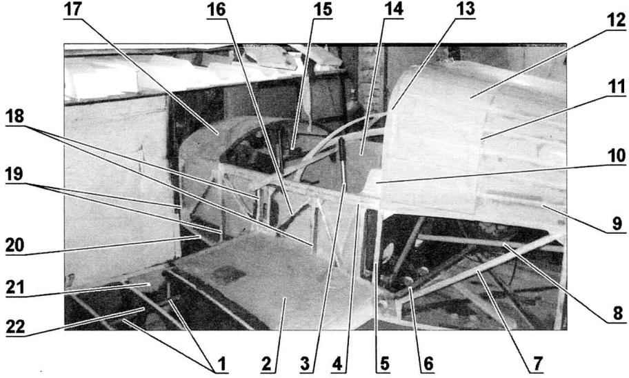
A fragment of the Central part of the airframe:
1—control rod Aileron; 2—left fuel tank; 3 — handle control plane (RUS); 4—upper spar (reinforced part); 5—the third frame; 6—shaft control flaps; 7—brace of the frame of the fuselage; 8—pull Elevator control; 9—stringer fairing; 10—seat; 11—the handle of the fairing; 12—casing of the fairing; 13—arc security; 14—inner lining of the cabin; 15—the installation location of the dashboard; 16—strut centroplane rack. 17—instrument compartment; 18 — front; 19—frames (first and second); 20 — lower longerons of the fuselage; 21 —spar wing; 22 — rib wing
The rudder — single-spar structure. On the spar-mounted return hinge lugs of the rudder on the keel and hog control. Ribs — plywood. Cavity sock filled with foam. The whole surface of the helm are covered with two layers of fiberglass.
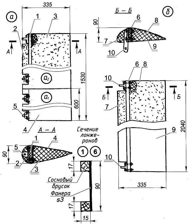
The constructive scheme and of the flap (I—centroplane part A2—console side) and b—Aileron:
1 —spar of the flap; 2—the toe of the flap; 3—flap; 4—casing (two layers of fiberglass in epoxy binder); 5—eyelet attachment of the flap to the wing (4 PCs); 6—spar Aileron; 7—toe Aileron; 8—Aileron; 9—a lining (two layers of fiberglass in epoxy binder); 10—lug bracket hinge Aileron on the wing (2 PCs)
Landing gear — tricycle, tail wheel, adapted to operate the aircraft from unpaved runways. Main support is spring type, provided with two brake wheels size 400×120 mm. Two racks-spring section 90×14 mm long 850 mm is used from the car KAMAZ. The spring mounting for the main spar center section is made using welded bracket made of steel (30KHGSA) sheet with a thickness of 4 mm With the aid of another (also welded) bracket to the lower end of the spring is attached to the axis of the main wheel.
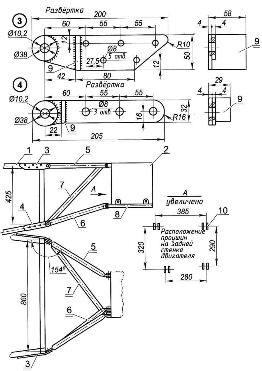
Engine mount:
1—longeron of the fuselage; 2—engine; 3 — upper eyelet elements of the motor to the fuselage (steel, sheet s4. 2); 4—lower eyelet elements of the motor to the fuselage (steel, sheet s4. 2); 5 -stretching (steel pipe d25,2pcs.); 6—spacer (tube d25, 2pcs.); 7—brace (pipe d25); -sub connection (pipe d25,2pcs.); 9—stop (steel, sheet s4); 10—location of the eyelets on the back of the engine
The size of the tail wheel 250×80 mm. Tail wheel — also automobile spring leaves, only a cross section of 80×10 mm and shorter (its length is 420 mm). Attached at one end to the fuselage with two bolts M10. On the other (rear end mounted (suspended on the axis of bolt M14 without bearing) fork wheel with a horn control over it.
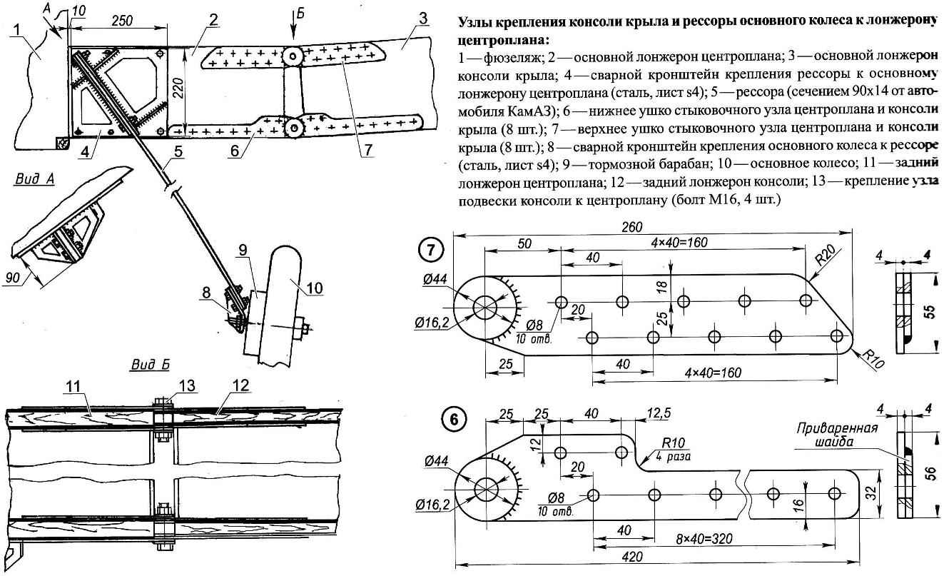
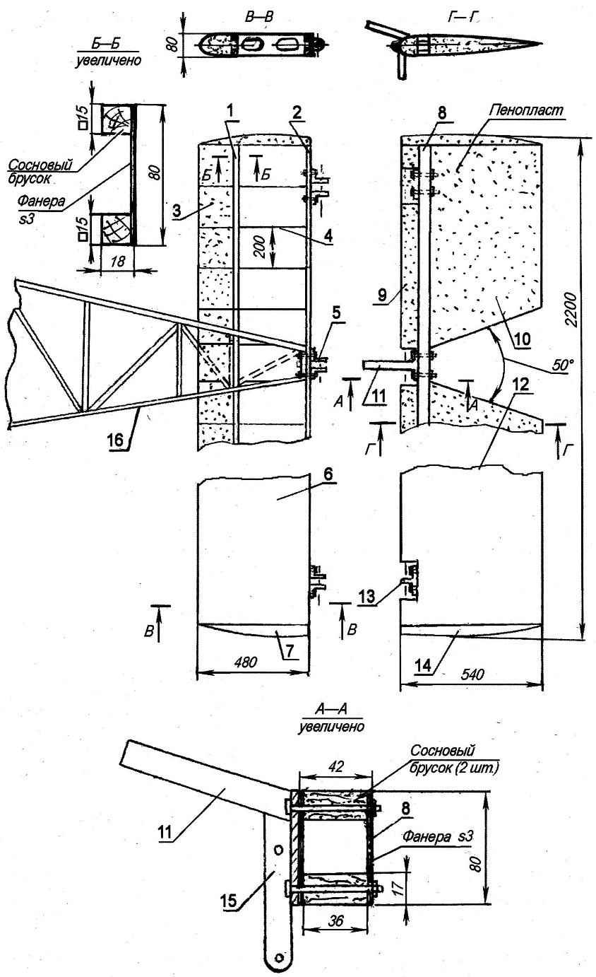
The attachment points of the wing and the main springs of the wheel to the spar center section:
1, the fuselage; 2—the main spar of the center section; 3 —the main spar of the wing; 4—welded the bracket springs to the main spar of the wing (steel, sheet s4); 5—spring (section 90×14 from trucks); 6—the bottom lug the docking station of center and console wing (8 PCs); 7—eyelet connecting the top node of the center section and wings (8 pieces); 8—welded bracket of main wheels to the suspension spring (steel, sheet s4); 9—brake drum; 10—the main wheel; 11 —rear spar of the center section; 12—rear spar of the console; 13—mount console mount Assembly to the center section (bolt M16 4 PCs.)
Wheel main landing gear equipped with brakes of drum type. The action is shown via the cables from the trigger left pilot and from the pedals — the right pilot.
All wheels are equipped later with fairings, is laminated into the foam matrix of fiberglass epoxy resin.
The cockpit — double, with the location of the pilots “side by side”, is located between the first and third frames To the upper cross member of the second frame is fixed dashboard. Seat pilots — foam, with a base of plywood on top covered with cloth type “flock”, which sheathe car seats with harnesses All their attachment points are connected with the power elements of the fuselage structure. The cabin still sheathed inside with fiberglass STEF-05. Cabin floor — from 6 mm plywood glued under the pedals rubber mats-footsies.
The scheme of fastening seatbelts:
1 —the shoulder straps the left of the pilot; 2—shoulder straps the right of the pilot; 3—waist straps of the left of the pilot; 4—the lap belts right of the pilot; 5— seat pilots; 6 — seat pilots; 7—shelf
The cockpit glazing is made of plexiglass thickness 3 mm Lantern — with two flip-up pieces (“Seagull”).
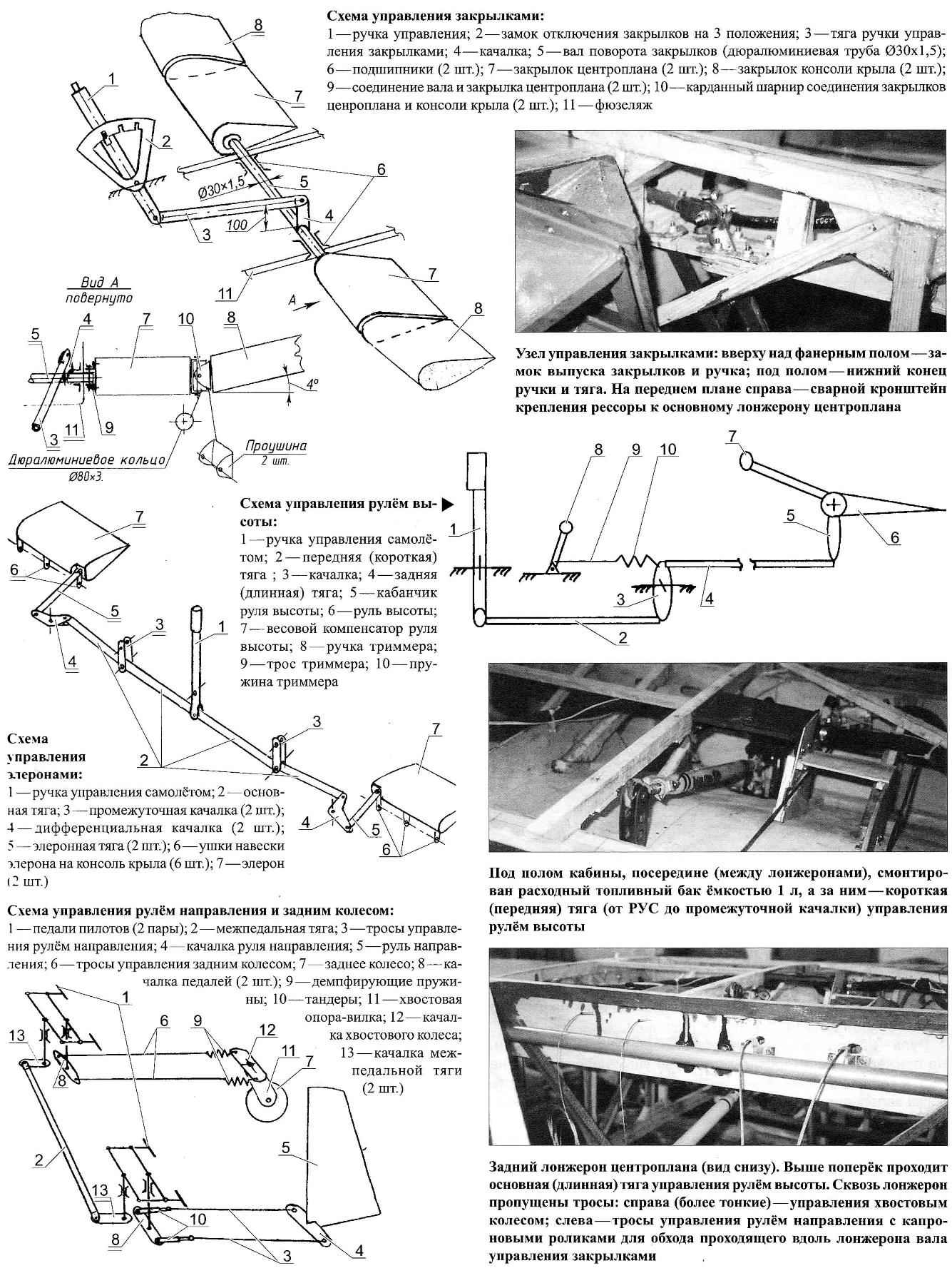
The aircraft control stick (RUS), mounted on a linear> cockpit between the pilots. Throttle opening of the carburetor of the engine is carried out from the handle control engine (ORE) that is installed on the left side of the cockpit. Here is the control stick trimmer of the Elevator and next to the floor — handle flaps.
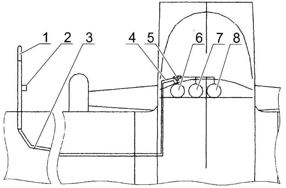
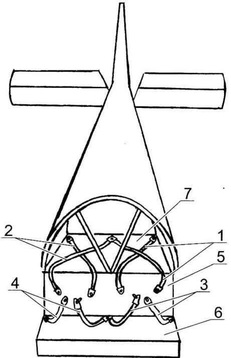
The layout of the aneroid devices:
1 receiver full of air pressure; 2 — receiver static air pressure; 3—a hose full of pressure; 4—static pressure hose; 5 —splitter (tee) static pressure; 6—speed indicator; 7—altimeter; 8—variometer
Power supply equipment and devices provide 12 V batteries with a capacity of 38 Ah; generator 12 V 1 kW, three Converter 36 In x 400 Hz.
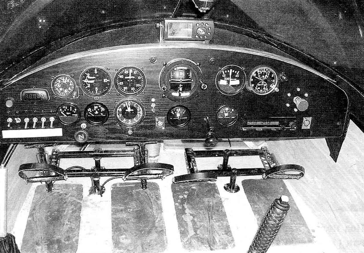
Dash Board, under it — the pedals control the rudder and tail wheel. In the foreground is a BLONDE, left—stick control flaps
The aircraft has on Board radio IC-A200, and also requires a set of flight and navigation instruments for flying in normal weather conditions.
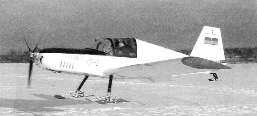
F-3 in winter, equipped with ski landing gear operation from snow covered airfields. Ski — dural.
Refueling of the aircraft through the neck in the left tank with overflow of fuel through the supply tank to the right.
O. FEFELOV, Kingisepp, Leningrad region
Recommend to read
 KITCHEN PENDANTS
Kitchens in most of our homes. Set of kitchen furniture is too small and rather monotonous, if not standard. But utensils and other kitchen household utensils is enough to place it in... WITHOUT A BRUSH AND IS CONVENIENTLY
Offer an easy and convenient option of using paper glue sold in plastic bottles without a brush. On the lid of the bottle make a hole with a diameter under the core-tube of a ballpoint...
 In our city of Kingisepp were gliding club ROSTO, which I have since 1996 worked as a flight instructor. Of aircraft in the club were two light aircraft, four airframe. But they were not new. Money to buy new aircraft or the repair of old growth is no longer isolated. Aircraft equipment came into disrepair, and in 2000 the club was liquidated.
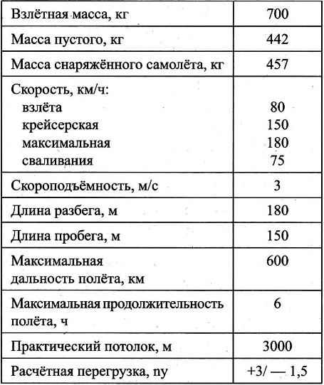
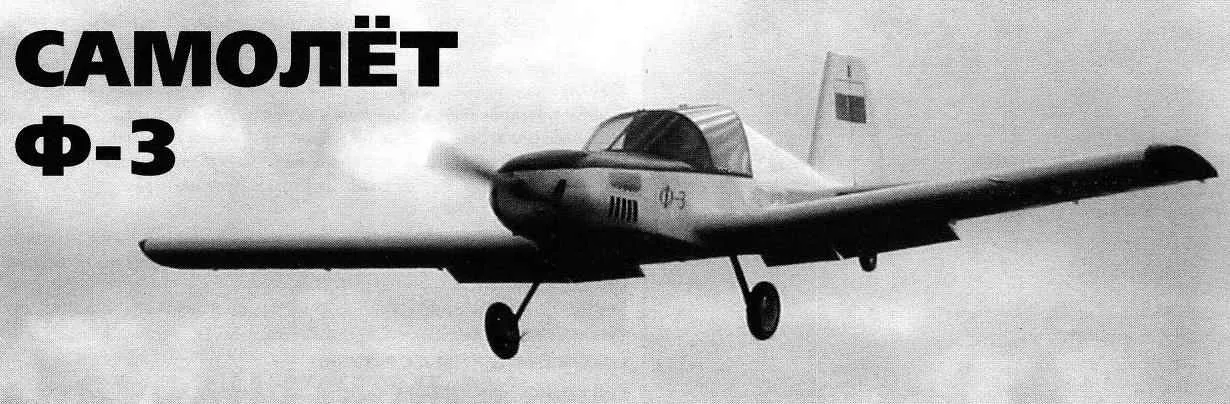
 Then became a professional pilot: graduated in 1986 Buguruslan flying school of civil aviation (and in 2004 the St. Petersburg Academy of HECTARES). Therefore, not represent my further life without aviation and decided on their own and with their own money to build the plane. From old colleagues, few believed that from this invention something will turn out: after all, even to build an airplane is not so easy, and still have to get the airworthiness certificate, the state room to fly it officially. In the end, having overcome many difficulties and obstacles on this path, I implemented the plan and built a double low normal aerodynamic configuration with a tractor propeller with the engine VW 1600 firm “Volkswagen” with a capacity of 60 HP, air-cooled. In October 2002, she performed on its first flight. In September 2003, registered the plane in FLA, under the designation of f-1 and got the tail number.