Pyramid mount towing lock and the dashboard is made from unequal angle (25×3 mm) duralumin brand D16T. Towing lock design is similar to that used on light training gliders and it is made of sheet steel of grade St 20 with a thickness of 3 mm, hook lock sheet steel with a thickness of 5 mm.
The fuselage is going in this order: connecting a longitudinal beam, on which are mounted all the accessories with the pole of the rotor gussets, install the cross beam. It should already be mounted to the axle of the wheels and lower the attachment points of the struts. Then use the struts perpendicular to the pylon is fitted to the cross beam in such position is fixed by lock nuts. The goodness of fit test, pulling between the extreme points of the structure steel wire. After that, obtained by setting the d-pad on level ground and securing it fixedly, mounted the pilot’s seat, a pyramid of mounting the towing lock, empennage and landing gear wheels. In the last turn is mounted preassembled on the hub of the rotor.
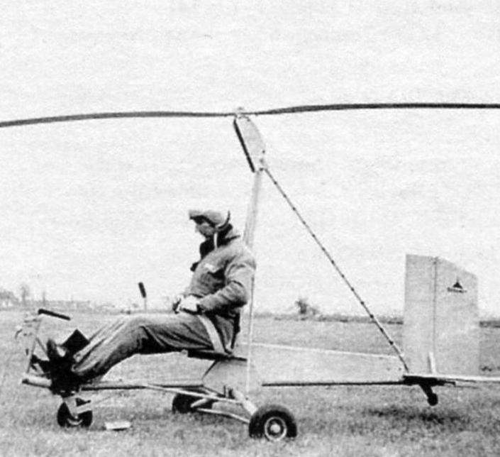
The autogyro:
1 – controlled wheel size 150×80 mm; 2 – brake plate, D160 s. 2; 3 – pyramid (D160, area); 4 – towing lock; 5 – handle (steel 30KHGSA, Ø35×1; 6 – pilot’s seat (steel 20, Ø 20X1,5); 7 – webbing (kit); 8 – backrest pilot (FAB and PS-1); 9 – pylon (D160, Ø65×2); 10 – blade rotor (FAB and foam); 11 – farm of the rotor hub (D16T); 12 – upper attachment point of the struts (steel 20, sheet s5); 13 – supporting roller (D16T); 14 – beam-fuselage (D16T, Ø65×2); 15 – Kiel (FAB sheet s 1, pine rail); 16 – the rudder (FAB sheet s1, pine rail); 17 – tail pulley (D16T, rubber); 18 – foot pedal control front wheel D160, angle; 19 – rudder pedal (ash); 20 -front brace (OBC Ø3); 21 – thunder M5 (finished product); 22 – cross beam (D16T Ø65×2); 23 – main wheel landing gear (300×125); 24 – thunder M5 (finished product); 25 – anti-flatter load (20 steel sheet s1, lead); 26 – trimmer blades (D16T sheet s1,5); 27 – rear brace (OBC Ø3); 28 – rudder control horn (steel sheet s2); 29 – thunder M3 (finished product); 30 – control cable (Ø2. 2); 31 – brace (D16T Ø35×1); 32 – control rod (D16T Ø28×2); 33 – upper plug (steel 30KHGSA Ø20×2); 34 – lower plug (steel 30KHGSA t Ø20×2); 35 – the lower attachment point of the strut (the steel 20 sheet s3); 36 – shape solitaire mounting pylon to the beam (steel 20 sheet s5)
Design details, made of steel, must be covered for protection against corrosion of first soil АГ10 or 138, then nitropaints bright colors. Fine detail (gusset plate and bolts), preferably galvanized or kadrirovat. Details of the tail primed and painted in the usual way.
CONTROLS
The autogyro in flight, as the plane has the ability to move and to be controlled relative to three axes: vertical, longitudinal and transverse. The deflection of the control stick the gyro entails the inclination of the plane of rotation of the rotor, thereby creating the desired pitch moment, or roll. Directional control of the gyroplane as the plane is a rudder mounted on the keel in the rear fuselage.
The movement of the handle and the pedals on the gyroplane complies with the established practice of flying an airplane, which is based on instinctive movements to maintain balance.
The basic General requirements applicable to the control autogyro, we present the points – for the convenience of pre-flight checks. This:
1. Sufficient stiffness control.
2. The minimum delay of control due to friction, backlash and deformation. It should not exceed the value defined by the speed of reaction of the person (1/7 sec).
3. Moderate effort on the handle and the pedals. In their deviation from the neutral position it is desirable that the efforts they were increased gradually and was directed in the direction opposite to the deviation (so-called positive gradient of effort on the handle).
4. Absence of vibration. Should not be “driving” handles and “twitching” of the pedals.
5. Survivability and durability. Rotating parts – bearings, ball joints and the fingers must have the required durability.
6. The independence of action of the longitudinal, lateral and directional control. For example, the deflection of the handle in the longitudinal direction should not cause roll.
7. The lack of jamming in the wiring and control mechanisms the deformations of the fuselage and other parts of the gyroplane, which is the transaction management.
8. The presence of limiters of longitudinal deviations of handles and pedals, which should be put directly on them.
9. The stock of the deflection angles of control devices (a few more than is required by calculation or experimental data).
10. Lubrication and protection of hinges and moving parts from dust and moisture in the joints of control.
11. Easy inspection, installation and dismantling management.
The mechanism of control autogyro (Fig. 1) consists of the control stick 2, the lower support 10, the bottom plug 8, two rods 4, the upper plug 7 and the upper support 12.
Handle mounted on the longitudinal beam of the fuselage 1 by means of a bolt about which it can oscillate in the longitudinal plane.
The movement of the handle in a transverse plane is transmitted to the plug through a shaft mounted on bronze bushings in the housing lower support. On the shaft handle and the bottom plug are attached with M6 bolts, from fork (if necessary) are placed on the shaft shims to eliminate axial play. From the bottom plug the power is transmitted to the upper by means of two rods, the ends of which have lug bolts with ball bearings. Top fork mounted on the axis of the rotor, which, in turn, is pivotally mounted on the shaft upper support.
Thus, the movement of the control stick in any direction will result in a deviation of the rotor axis in the same direction.
The most important details in the mechanism of management are fork (Fig. 2 and 3) and their tips (Fig. 4). Therefore, in their manufacture it is necessary to pay special attention to the quality of machining. Welds should be smooth, without shells and slag inclusions.
Feathers forks after bending shall not have cracks, wrinkles and burn-through. To detect cracks, lack of penetration is best, if possible, x-rays parts, or at least after heat treatment and cleaning them with sand to hold the magnetic control.
Welding of the plug is desirable in specially made stocks arc welding. This ensures compliance with the geometry of the part drawing and get rid of difficult and responsible operations – changes. Immediately after welding, the plugs should be subjected to a heat treatment according to the drawings. After the heat and sandblasting scans are processed the Central cups at the size of the inner diameter 24 and the ends of the plugs up to a diameter of 18 for the installation tips.
Fig. 1. Control system main rotor of the autogyro:
1 – longitudinal beam (fuselage); 2 – handle; 3 – pilot’s seat; 4 – thrust (left); 5 – pole; 6 – cheek pylon; 7 – upper plug; 8 – the lower plug; 9 – body; 10 – cheek support; 11 – stop; 12 – the case of the upper support; 13 sleeve; 14 – washer; 15 – pin Ø2 mm; 16 – plug top; 17 – rod tip; 18 – tip of plug; 19 – piston Ø6х1 mm; 20 – head SHS-10; 21 – washer; 22 – cotter pin Ø1,5 mm; 23 – a nut; 24 – lug-bolt; 25 – a nut; 26 – lock washer; 27 – the piston Ø8×1 mm; 28 – stand housing; 29 of the sleeve; 30 – shaft-adapter, 31 – lower plug
The tips of the forks are machined according to the drawing (Fig. 4), but diameter 10П2а and 18 left rough 1.5-2 mm. In this form, they are subjected to heat treatment, and then face piercing holes, the seats to the desired size. Particular attention should be paid to the quality of the processing indicated in the drawing, the radii of mates and sureshbabu grooves.
During Assembly by fitting the mating parts and installation (where required) of shims are required to ensure the smooth operation of the entire control mechanism without jamming and backlash. All nuts should be secondline cotter pins, lock washers or secernere according to the drawing (Fig. 1).
Directional control of the gyroplane, as mentioned above, is the rudder. Mechanism of directional control represents neither constructive nor technological difficulties, and its structure and operation is easy to understand of General arrangement drawing of the autogyro. The dimensions of the keel and rudder can be removed from the same drawing, increasing them in accordance with the scale. The tail of the gyroplane is easy to fabricate by cutting parts from plywood sheet with a thickness of 10 mm. In this case, the keel will have to put the brace wire OVS diameter of 1.2 – 1.5 mm. the Other ends of the braces through the M3 turnbuckles are attached to the cross beam at the junctions of struts.
A disadvantage of the plywood structure of the plumage is slightly more weight than the tail, made of a set of ribs with a shell of mm plywood. Advantage – simplicity.
To ensure the controllability of the gyro relative to its longitudinal axis, the deflection directions should be 25° right and left from the neutral position. To ensure the handling on pitch and roll axis of the rotor of a gyroplane should be 12° in either direction from the neutral position.
Yu RASUK
Recommend to read RC MODEL BIPLANE The desire to build a model of a biplane under the existing engine MDS-6,5 KU initially led to the search for analogues. View magazines and catalogs helped to decide what I would like to... INTERTUBES If you have under the sink plumbing fittings is not covered — to hide all this ugly picture will be easy and simple if you use a thin plastic sheet, from which it is easy to twist the... 
 In the latest issue of our magazine published a series of articles of the group of designers of the gyros about the features of the construction of these helicopters, how to build gyroplanes, how to fly them, towed by boat or car. In this room we talk about the fuselage structure and the governance of the autogyro (or Meropenem, since they are identical).