Similarly, the sheathed side. After finishing this work, the case can be removed from the pile and proceed to frame interior stringers, which are the trim and increased top side. It is necessary to carefully calculate their length or use the method of successive approximations (to paraphrase a famous saying — cut it seven times!). Between the outer and inner stringers are glued spacers with a thickness of 20 mm with step of 300 mm, Two spacers need to be strengthened — they will be used as the basis for rowlocks.
The joints between the sides and transom and between the sides and the nose frame reinforced angular brackets, sawn from plywood with thickness of 6 — 8mm and secured to the housing section by screws and glue.
Fig. 4. Sealing the sides:
1 — insert (pine 18X45X50 mm), 2 — stringer, 3 — inner stringer, 4 — rail, 5 — casing, 6 — screw.
Fig. 5. Cross member to install sverzov:
1 — nut-“lamb”, 2, 6 — puck, 3 — puck-pad (glued with epoxy), 4 — swiercz, 5 — pin threaded M12, 7 — bolt crossmember-to-body, 8 — steel plate (3X90X125 mm) 9 — cross (oak or beech 20X90 mm), 10 — bolt M6 nut
Fig. 6. Install the crossmember on body:
1 — crossbar, 2 — stringers, 3 — pad (plywood 8Х55Х100 mm), 4 — bolt M6, 5 — Board, 6 — strip (tree).
Additional parts are cut from pine boards or plywood with a thickness of 15 — 18 mm. Their cross-section resembles a biconvex symmetrical profile of the aircraft wing. At the top of sverzov on both sides of each must be affixed to the plywood (8mm thick) pads. The wheel of a sailboat — from desyatiletnego plywood; the tiller is pivotally connected to the wheel — from the oak bar.
At the end of these works you can start to finish. It is preferable to hang it outside on fiberglass epoxy glue, but it is not restricted just to luted, primed and painted in the desired color. Steering wheel, additional parts and banks should be impregnated with hot linseed oil n ulcerate.
Sailing rig of a Dinghy — Latin, with an area of 4.5 m2. The mast is fixed at a distance of 760 mm from the nose (additional parts in this case are located at a distance of 1220 mm from the nose). To determine the center of the sail and the centre of lateral resistance, you can use the following methods. For triangular sails (which is Latin) its center is determined as the intersection point of median lines dividing the side opposite the corresponding angle in half. The center of lateral resistance of the hull of the Dinghy is the easiest way to find empirically. For this, the estimated (purely roughly!) the centre of lateral resistance — the Board is bound by the rope and pull the boat sideways through the water. If the state change CH, the candidate center is selected incorrectly and the anchor point should be changed to ensure that the boat is moved strictly sideways. The place of attachment of the rope will be a true centre of lateral resistance.
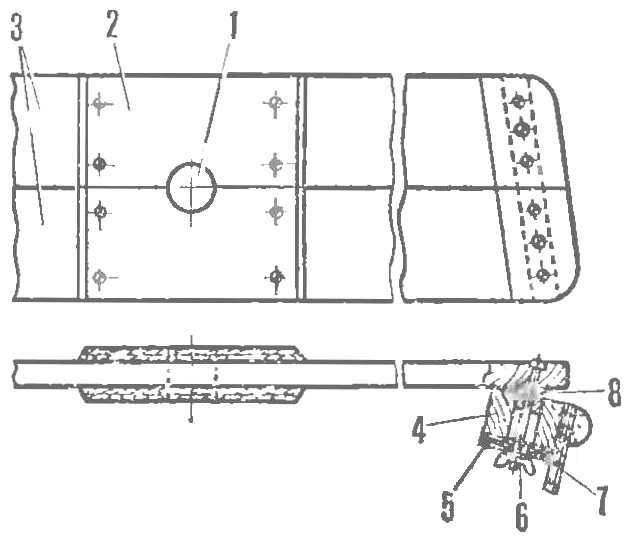
Fig. 7. Cross — bearing for the mast:
1 — hole mast 2 — pad (plywood 8X175X175 mm), 3 — the details of the cross-beams of pine (20X90 mm), 4 — inner stringer, 5 — panel (plywood 8X55X150 mm) 6 — M6 bolts, 7 — trim bead, 8 — strip (tree).
Fig. 8. A — the relative positions of the center of the sail (CPU) and the centre of lateral resistance (MKS) Dinghy:
1 — sail, 2 — body, 3 — swiercz (dash-dotted line shows the way of changing CBS to turn sverzov); B — geometrical method of finding the CPU; — practical way of finding TSBS: 1 — the attachment point of the rope behind the selected CBS 2 anchor point ahead of CBS, 3 — anchor point coincides with the TSBS.
Fig. 9. Sailing rig of a Dinghy:
1 — jaw, 2 — solitaire head points of the angle of the sail with grommets, 3 — pocket, 4 — Klondike solitaire the tack angle with eyelet, 5 — boom, 6 — mast, 7 — pocket, 8 — solitaire Shkotovo corners with grommets.
With the installation of the mast and sverzov need to ensure that the centre sail were located at 100— 150 mm closer to the nose than the center of lateral resistance.
Mast height — 3200 mm. Diameter near the base — 60 mm, in the upper part is 40 mm. the Gaff and boom sails — aluminum tubes Ø30—40 mm and length 3000 mm. it is possible to make them from pine sticks of appropriate length. The gaff and boom are connected with a sail with pockets sewn to the main panel.
A small area of the sail allows to do without a complex system of blocks. You will need only one unit, mounted on a swivel on Kileva the Board, and two to three meters of vegetable or nylon rope (for the geek-sheet).
Recommend to read
 AS I DO MOTORCYCLES
The motorcycle design is not less exciting than any other vehicles. Besides the motorcycle, which are, in fact, the bare concept of a self-propelled mechanism, requires greater design...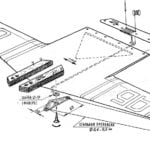 “FIREFLY”
This simple and reliable model was developed in the Chisinau children's club "Firefly" under the leadership of Alexander Pavlovich Marchenko. All modelers-beginners, writes...

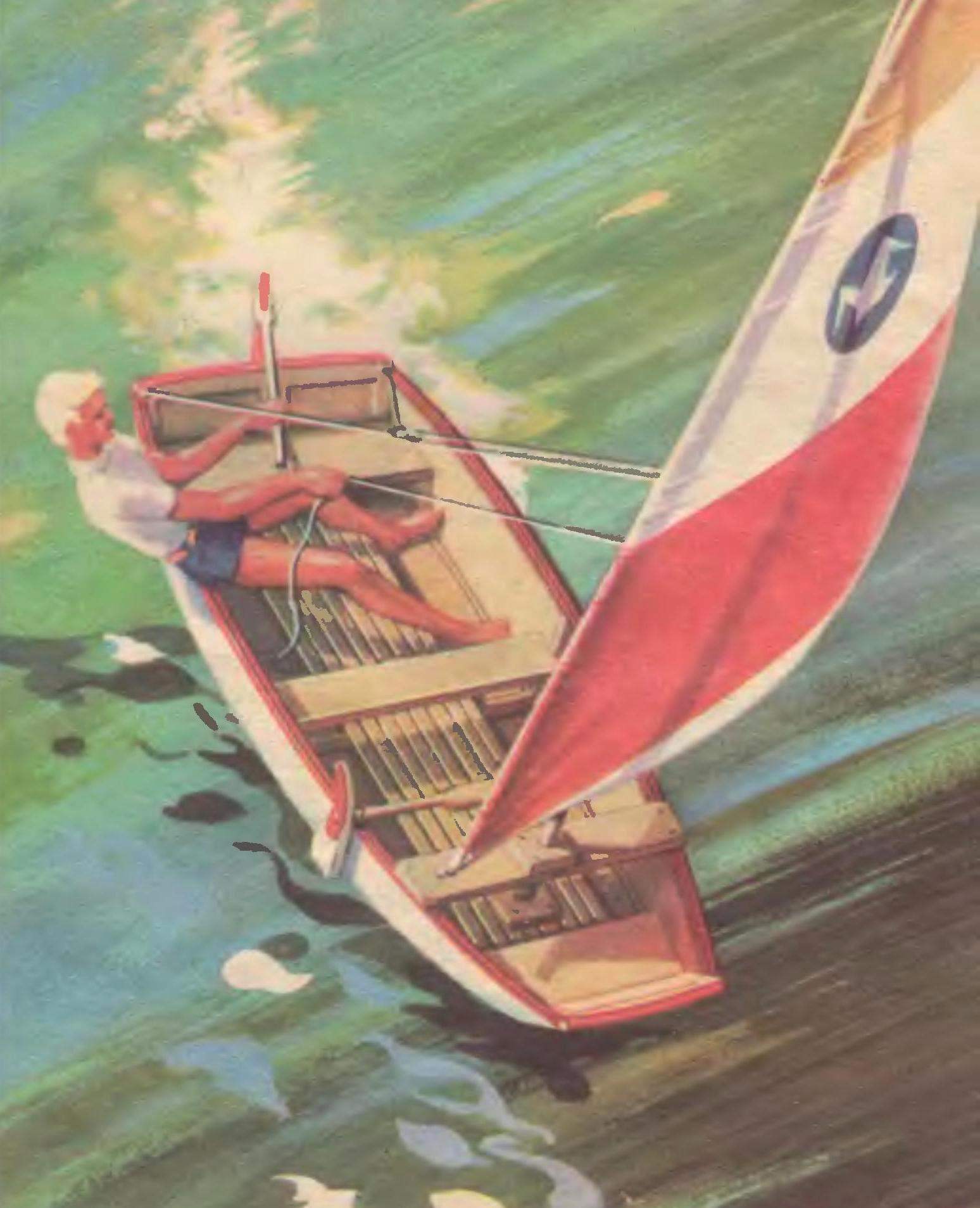 If you live not too far from the pond, make our drawings Dinghy, and you will experience all the delights of sailing. But if this ancient engine is not too attract you, the body of the Dinghy can be used as the basis for small motor boats or rowing Dinghy. Materials for it will require only two sheets of plywood and pine slats.