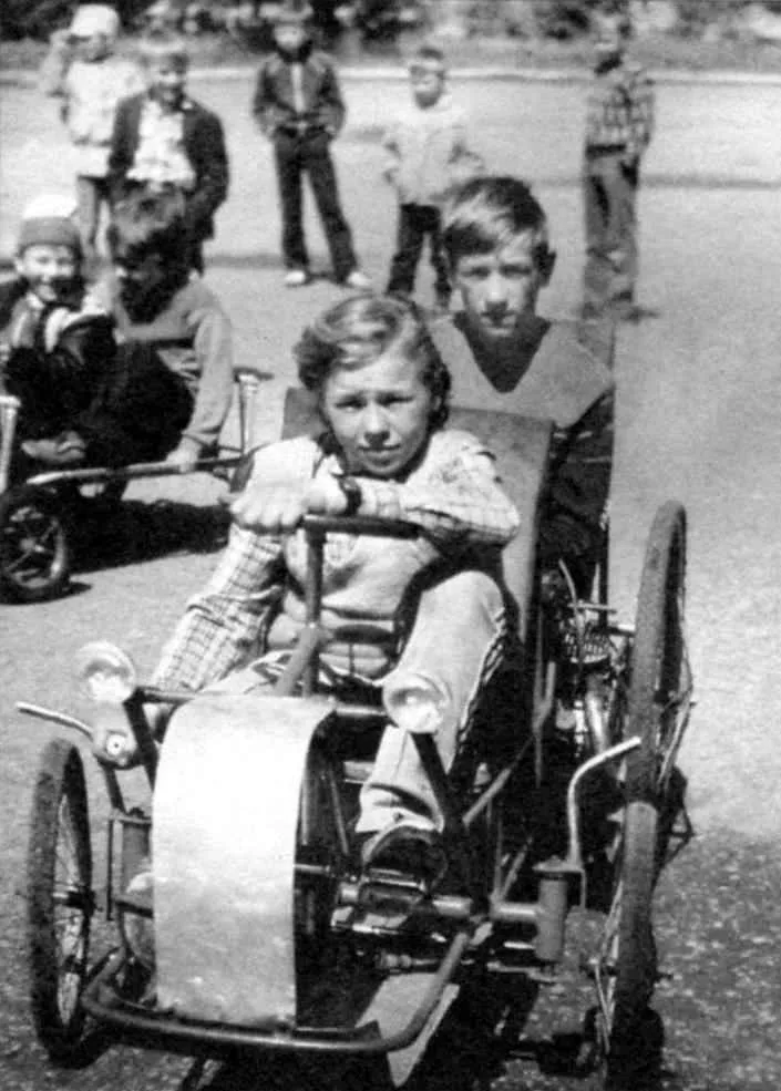
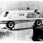
 Double Belomorkanal “Tandem” is my latest self-made design with a combo drive from pedals, driver and passenger (in this case, he becomes the second member of the crew), and two-stroke moped engine D-6 working volume of 50 cm3 capacity of 1.2 HP (maximum speed — 4500 per minute).
Front steering wheels — heavy duty off the bike “Kama”, and the rear drive from the bike “Ural”, revised (with extended hubs).
The source material for “Tandem” served as a velomobile, which is already cited in the “M-K” № 7, 2008.
The new recumbent frame and truss design (in the form of a trough). Welded from thin-walled round pipes from decommissioned bus handrails and handles of the bed. Consists of two tubular spars, the front arc-bumper, front, beam-axle, rear beam, several arcuate cross members and a pair of rear trailing links-supports for the ends of the axles. The spars are made of pipe outer diameter of 40 mm as one piece in arc shape, converging from behind. In the front part welded to the side members of the front axle beam made of the same pipe. To the ends of the beam are welded bushing steering knuckle.
To the front beam welded arc-bumper and tilted forward under-steering the portal (later the space between them is covered by the dural cone, under which is the trunk). The portal is welded console steering column plate at the end. All of these parts are made of half-inch pipe. From the same pipe, and multiple arcuate cross-members between the spars, giving the frame “hat” shape. On them the plank floor of duralumin sheet thickness of 1.5 mm.
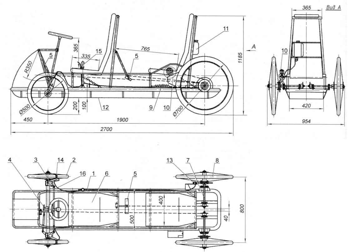
Belomorkanal “Tandem”:
1 — frame;
2 — front wheel (off the bike “Kama”, 2);
3 — the knuckle of the front wheel (2 PCs.);
4 — steering gear (rack and tie-rods);
5 — pedals (2 PCs.);
6 — seat (2 PCs.);
7 — axis rear wheels (2 PCs.);
8 — rear wheel (off the bike “Ural”);
9 — spring and cable reverse drive pedals (2 PCs.);
10 — engine D-6;
11 — fuel tank;
12 — the bottom (dural sheet 1.5);
13 — disc brake rear wheel;
14 — tick-borne brake on the front wheel (2 PCs.);
15 — lever control brake and “gas” engine;
16 — the brake cable
Along the frame sides are made parapetti of thin-walled tubes with outer diameter 15 mm, passing near the seat back (second) member of the crew at the rails. For them it is convenient to hold while pedaling, and just when the trip — wheel-it does not have.
The elements of the frame can be attributed to the low U-shaped rack-support seats driver and passenger, as well as high rack-support their backs, made in the form of trapezoidal portals. Those and other racks rely on the spars and strap them down.
The seats themselves, or rather their foundations, made of duralumin sheet thickness of 1.5 mm (by the way, from the same sheet flooring and front fairing). The seat cushions and backrest are made as a single piece of foam rubber 50 mm thick and covered with light leatherette.
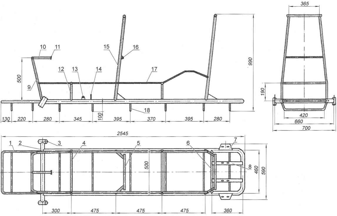
Frame:
1 — bumper (steel pipe d20);
2 — cross member (steel pipe d40);
3 — sleeve knuckle (steel pipe d40, 2 PCs.);
4 — bearing seat (steel pipe d20, 2);
5 — cross member of the seatback (steel pipe d40, 2 PCs.);
6 — cross member to the longitudinal supports of the axle shafts (steel pipe d30);
7 — the supporting base of the bearing housing 203 of the driveshaft (steel sheet s4, 2 PCs.);
8 — longitudinal support bearing housing 202 of the driveshaft (steel rolling area 32×32,2);
9 — stalk portal (steel pipe d20);
10 — console (steel pipe d20);
11 — mount plate steering shaft (steel sheet s4);
12 — front seat supports (steel tube d20,4 PCs.);
13 — eyelet control lever engine and brakes (steel sheet s4);
14 — strut mounting of the rope brake (steel pipe d15);
15 — side seat strut (steel tube d20, 4 PCs.);
16 — lug suspension pedal rod (steel sheet s4,2 PCs.);
17 — parapet (steel pipe d20,2pcs.);
18 —curved cross bar (steel pipe d20, 8 PCs.)
Rear axle consists of two half shafts mounted on a frame rigidly (without suspensions), which greatly ensured the simplicity of the design. Each half shaft has two bearings, housing one of which is fixed to the platform, welded to the spar, and the other additional longitudinal support of the area with dimensions of 32×32 mm.
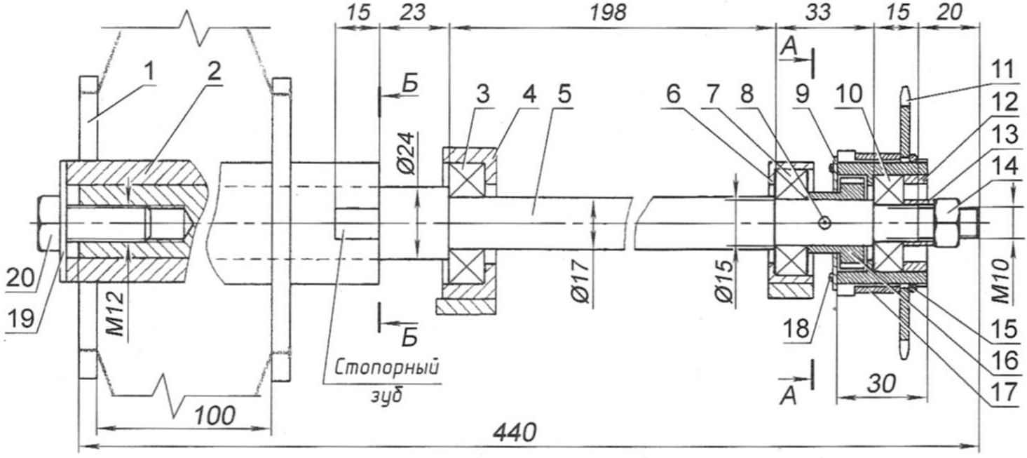
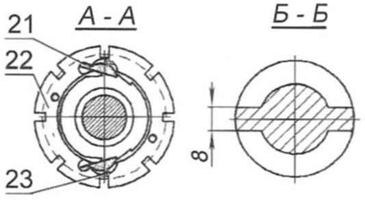
Drive half shaft of the rear wheel Assembly:
1 — the rear wheel;
2 — sleeve rear wheel;
3 — the bearing 203;
4 — the bearing housing 203;
5 — driveshaft (steel 45, the range d24);
6 — the bearing housing 202;
7 — the bearing 202;
8 — pin (steel 45, the range of d4);
9 — cover;
10 — bearing, 201;
11 — a star (off the bike HWS);
12 is pressed on the locking sleeve;
13 — thrust sleeve;
14 — nut M10;
15 — retaining ring;
16 — ratchet (off the bike HWS);
17 — spacer sleeve;
18 — M4 screw (4 PCs.);
19 — thrust washer;
20 — screw M12;
21 — doggy (from the bike HWS);
22 — hub sprocket;
23 — return rubber band
Front suspension — springs mounted on the axis of the steering knuckle. But since the course of the suspensions is quite small, then to mitigate the impacts from a significant pothole on the upper ends of the axles installed bumpers of soft rubber.
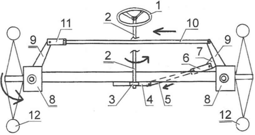
Steering control scheme:
1 — steering wheel;
2 — steering shaft;
3 — pinion steering mechanism;
4 — rack of the steering mechanism;
5 — short pull;
6 — threaded sleeve adjusting the length of the short rod;
7 — eyelet short thrust to the knuckle;
8 — steering knuckle (2 PCs.);
9 — knuckle (2 PCs.);
10 — long (nikolena) thrust;
11 — threaded sleeve adjusting the length mikolasko rod;
12 — front steering wheel (2 PCs.)
Each crew member has an oscillating (push) actuator with a pair of reciprocating pedals and a chain drive on one wheel: drive from La to the left, from the passenger (second crew member) is on the right. Spremnosti pedals allows in difficult conditions the crew to work (push the pedals) with both feet. Chain and sprocket — bike with a pitch of 12.7 mm Number of teeth z=24. The chain length is only slightly larger pedals (it jumped directly to the sprocket) and pedal chain connected to a steel cable with a diameter of 3 mm. Reverse pedal (chain and cable) by means of a return tension spring (or as often speak, is normally compressed), mounted on the frame and connected with a chain.
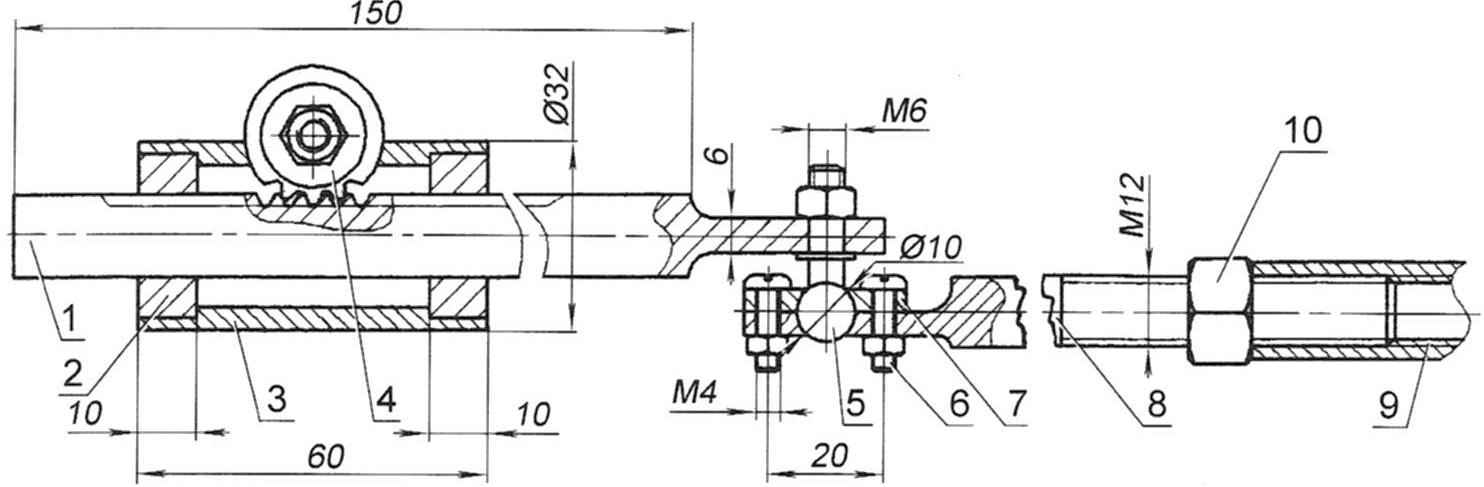
Steering rack and pinion:
1 rail;
2 — bushing (bronze, round d28, 2);
3 — housing (tube d32);
4 — gear;
5 — ball pin with nut M6;
6— болтМ4(4 PCs.);
7 — cover;
8 —joint with M12 threaded tip;
9 — screw-threaded sleeve adjusting the length of the short rod (pipe d16);
10 — lock nut M12
As mentioned in the beginning, the recumbent has a motor drive on the left wheel from the gasoline internal combustion engine D-6. The transmission of rotation from it to the wheel is of the stub-roller chain with a pitch of 12.7 mm. chain Tension is done by the roller, biasing the lower branch. Sprocket driven motor drive (the drive wheel) has 46 teeth. Motor control, as well as managing a recumbent, is only the first member of the crew.
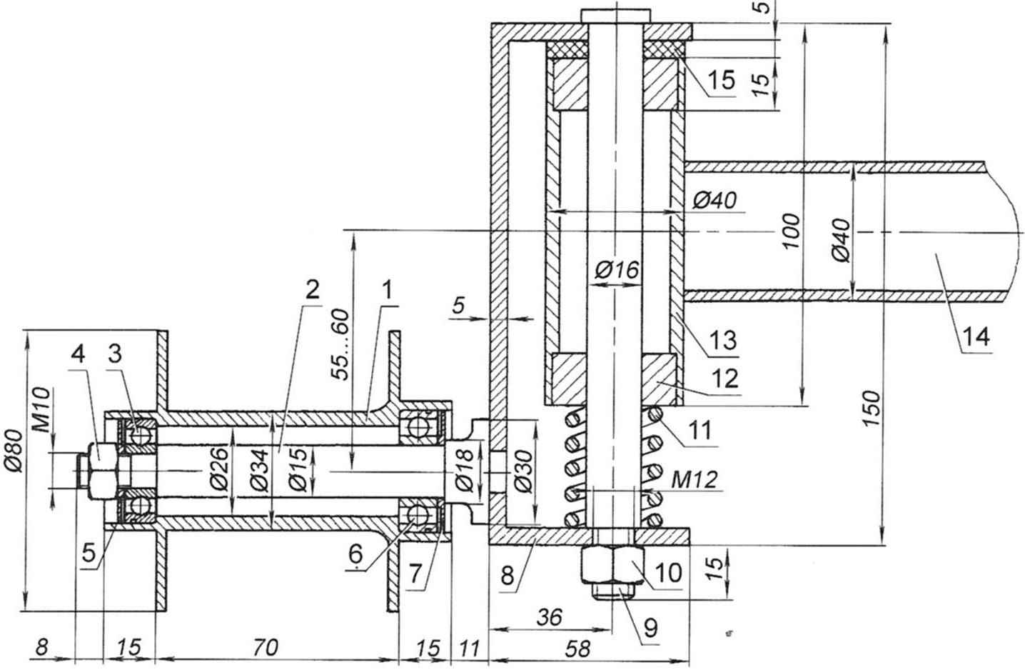
Steering knuckle:
1 — housing bushing front wheel;
2 — front wheel axis;
3 — bearing, 201;
4 — nut M10;
5 — outer boot;
6 — the bearing 202;
7 — internal boot;
8 — clip knuckle;
9 — axis steering knuckle;
10 — nut M12;
11 — spring;
12 — bushing (bronze, 2 pieces);
13 — bushing, steering knuckle;
14 — front beam;
15 — rubber bumper
On the right wheel mounted disc Parking brake. In effect it is driven by the floor lever located under the right hand of the driver moving. In the Parking lot he plays forward and is fixed. At the upper end of this lever is a manual lever, the trigger actuator of the main brakes of tick-borne type, acting on front wheels. Here is Motovilovka handle “gas” slide type, allowing to adjust the flow of fuel and don’t hold her constantly. The clutch shall be disengaged by a pedal located under the right foot of the driver.
Steering — automotive type. Consists of steering wheel with a tubular shaft, rack and pinion short (from the rail to the left of the wheel) and long (mikolasko) rods and steering knuckle. The steering shaft has two points of support: at the bottom it is inserted into the steering gear housing and has mounted gear rack and pinion drive; top — mounted clamp (rotatably) to the console plate is grounded portal.
A. MATVEICHUK, Zavodoukovsk, Tyumen region.
Recommend to read
 GLIDING CAR…
Curious views accompany this anipa everywhere. And no wonder — too unusual looks drown it in the car... a boat on wheels. We are talking about a vehicle that exists so far in a single...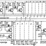 MUSIC BOX OUR DAYS
Since ancient times people admired the music box. Their creation was only very skilled mechanics, who had besides an ear for music. Now the progress of technology made it easier....
