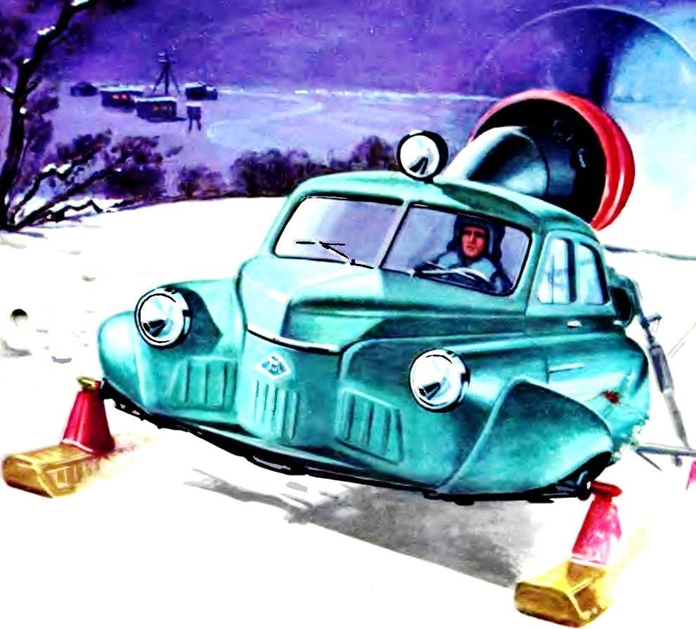
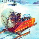
 In 1959, the USSR Ministry of communications has ordered the design Bureau of the famous Builder of helicopters N. I. Kamov unusual for this size car — a snowmobile. Developers were tasked to create a vehicle that could provide postal services in remote in the winter areas of the North, Siberia, Kazakhstan and Far East.
 A year later the first shipment of snowmobiles, called “North-2”, entered the post pine. They replaced worn out to the limit the previous releases snowmobile NKL-16 or NKL-26, which after the great Patriotic war “retrained” in connected cars.
Snowmobile “North-2” immediately won recognition. Comfortable, fast, roomy, they had a good cross in the harsh conditions of winter terrain. With their appearance on the mail routes became possible to provide regular mail delivery to the most remote settlements. Suffice it to say that in collaboration with civil aircraft, these snowmobiles were regularly deliver to Central and regional Newspapers on the day they are released in all the settlements along the Amur river in the area from Khabarovsk to Nikolaevsk-on-Amur, in the towns by the river Ob, where the planes were based in Khanty-Mansiysk and Salekhard, up and down the river Lena from the city of Ust-Kut and dozens of other points scattered across the North, Siberia and the Far East.
Average seasonal mileage of snowmobile on zip lines ranged from 12 to 15 thousand km per car at an average speed on the toughest winter roads 30-35 km/h. But the trails snowmobiles passed through deep virgin snow, hummocky ice, they had to work when the frost reaches —50—55°. No transport would not have coped with similar difficulties. How looked this good and such a reliable machine?
“Sever-2” — chetyrehlistnyj snowmobile with steerable front skis. The body of the snowmobile by road, is additionally insulated. Independent heating unit supported in the cockpit of zero temperature, provided heated windshields and warm up the engine before starting after long stops at low temperatures. Good glass body give the driver sufficient review, and powerful lighting equipment — headlamps with main and dipped light and spotlight-seeker — allowed trouble-free to operate the snowmobile in difficult weather conditions.

Fig. 1. General view and overall dimensions of the snowmobile “North-2”.
The body was divided into four compartments. The trunk was located under the front hood; it is attached to the battery, and the free space was occupied by the covers, which hid the engine at stops, and a necessary tool. The cabin in the front part differed little from the car, and the space behind the seat occupied cargo hold, which was loaded with mail parcels, Newspapers, letters. When required this compartment for folding seat could accommodate two or three passengers. And finally, was still the engine compartment, located behind where the car was the trunk. Above the engine compartment, at the top of the body, fastened closed easily removable hood internal combustion engine. It was established on under engine frame — tubular welded spatial farm, which was privertyvali stands bolted to the lugs of the rear frame of the body.
Place under the engine designers used under components and units of motor equipment. It housed: oil cooler with hoses for supplying thereto air from the intakes and nozzle, which was mounted leaf shutters; cylinders for compressed air and exhaust air system to allow starting of the engine; Autonomous heating system with separate fuel tank and the pipe feeding the heated air to the carburetor of the engine; the exhaust manifolds of the engine.

Fig. 2. The layout of the snowmobile “North-2”:
1 — pylon-ski, 2 — a cap of fastening of skis on the half-axis, 3 — headlight, 4 hood cap fuel tank 5 — front hood, 6 — trunk, 7 — battery, 8 — windscreen 9 — wiper, 10 — steering wheel 11 — spotlight 12 — internal partition 13 — Parking light, 14 — fairing, 15 — oil tank, 16 — hatch on the fairing, 17 — stationary ring of the hood, 18 — propeller, 19 — flap hood 20 — engine, 21 — bushing of the propeller 22 is a motor frame, 23 — fencing of the propeller 24, the air intake 25 — rear strut, 26 — heater 27 — bracket-ski, 28— rear ski, a 29 — axle shaft, 30 — strut axle, 31 — sealing of the opening for the rear wheels, 32 — the door of the cargo compartment, 33 — housing 34 — door of the driver’s cab 35 to the rotary axis of the front skis, a 36 — cone, 37 — fuel tank (left), 38 — bumper, 39 — front ski 40 — sole of the ski 41 is undercut skiing.
On the roof of the vehicle body, the front of the engine, on the lodgment housed the oil tank, closed fairing. Posledov served for the flow of air flowing under the engine hood, and to cool the cylinders. At the air outlet from the engine compartment were installed leaf shutters, by which the driver regulates the degree of cooling of the engine.
“Sever-2” with an aircraft engine of AI-14РС (gear, sled) designed by A. G. Ivchenko for the First time on the machines of industrial production, he spun a three-blade metal propeller with automatic adjustment of step and the introduction of the blades in the position reverse to obtain reverse thrust and braking the car. For security, the area of rotation of the propeller had tubular fence, painted bright red paint. On the outer ends of pipe fencing set the red and green marker lights.
The body of the snowmobile was connected with the ski elements front and rear suspensions. They consisted of axes, on which are mounted the skis and shock absorbers, smartasic shocks when driving on rough roads.
It should be noted that the serial body of the car “Victory” and its internal equipment has undergone only minor changes. In the front suspension skis were installed welded frame. She had a pad that rested on the spring shock absorbers and which were used by the automotive dampers. On the frame welded brackets for mounting elements of the front suspension ski steering and towbar. Formed under the front hood space from the bottom sewed up sheet.
To the front and rear wings on the bolts fastened the side flaps that cover the cutouts of the wheels. The space under the wheels used under fuel tanks. Top slotted holes of the approach to wash the filler necks of the tanks and the sensors benzinaio.

Fig. 3. The placement of the controls in the cab:
1 — floor cab 2 — pedal throttle control carburetor, 3 — pipe heating 4 — panel electroridopuncture, 5 — a switchboard with toggle switches and signal lights, 6 — front panel 7 — windshield, 8 — wiper 9 — wiper blade, 10 — instrument panel control plant, 11 — compass 12 — steering wheel, 13 — handle swivel floodlight, 14 — ignition switch-magneto 15 — the trunk for the documents, the 16 — opening doors, 17 — control knob (left to right): shutters motor, shutters oil cooler door heated air inlet in the carb, 18 — lock the front hood of the trunk, 19 — choke control, 20 — lever manual fuel pump 21 — the lever of the pitch control of the propeller 22 — crank plunger pump starter, 23 — air distribution knob ticking system start engine, 24 — “the box” starting pump 25 remote air system, 26 — the driver’s seat, 27 — stick, fire hydrants, 28 — edge air system, 29 air pressure gauge 30 damper control, the heating of the cabin.
Redesigned the dashboard of the car were fixed on rubber shock absorbers, and included the devices that monitor the operation of the propulsion system, and signal lamps. To the left of the dashboard and steering column put a fuse box with switches: control and signal lamps. Under the flap there was a bar electroridopuncture. To the right of the dashboard, below the box for documents brought control knobs louvers of the engine, the oil cooler and damper heated air inlet to the carburetor. Under the dash, on the floor fit remote control fuel and air systems. It installed a manual fuel pump, starting the pump starting the engine, the air valves and pressure gauge.
Car seat with the back preserved, and the cabin from a cargo compartment separated by a glazed bulkhead. Window walls and glass doors supplied metal bars.
In the rear shot design that separates the trunk from the passenger cabin and removed the rear passenger seat. Instead of the set shifted back partition, whereby increased capacity of the cargo compartment. It is mounted hard, a folding seat. In the folded position it is the second floor. The partition is provided a removable hatch that provides access from inside the cargo compartment into the engine compartment, oil radiator, engine and systems.
The rear window of the car body removed and replaced by a removable hatch, servants to approach the engine from the bottom.
On the lateral outer walls of the rear body work-hardened inlets, through which a counter flow of air via special ducts delivered for cooling the oil radiator. On the trunk lid of the car made a round hole to exit the tunnel cooler.
The underbody was also changed. Removed a number of minor brackets and components of automotive systems. Modified box inside which held the propeller shaft. His serving down the portion of cut and welded steel sheet flush with the bottom hull bottom. In the resulting tunnel has communication motor control and its components and the heating network, bringing warm air from the heater in the driver’s cab.
For secure attachment of elements of the sub-frame and rear suspension ski under the rear part of the body supplied welded metal frame consisting of two longitudinal spars of box section, connected by two cross beams. It is secured with spars to the front suspension units rear springs of the car and the beams of the underbody.
Ski snowmobile used interchangeably, riveted construction. They are made of aluminum in combination with steel welded elements. The body of the ski included cladding, transverse and longitudinal set — diaphragm and longitudinal profiles. Him riveted to a pylon, which serves as the mounting bracket of the ski to the axle of the suspension. It consists of a riveted base having a transverse partition connected with the frame of the ski, and a welded steel bracket with sleeve, which it fits over the axle shaft. This bracket is bolted to the base.

Fig. 4. Front suspension ski:
1 — struts 2 — the front beam of the hull, 3 — sinking spring, 4 — rubber stop, with 5 hydraulic damper, double-acting, 6 — the lever of the damper, 7 — tightening bolt 8 to the eccentric axis 9 — rubber stop, 10 — hour, 11 — stud fastening pin, 12 — bronze bushing bracket, 13 — thrust washer 14 — nut of fastening of skis, a 15 — car semi-axis, 16 — amplifying nozzle, 17 — bracket horn, 18 — hog the front of the ski, 19 — pin, 20 — bearing, 21 — axial bolt 22, the Cup spring 23 — bolt.

Fig. 5. Steering:
1 — potatoes, 2 — ball bolt, 3 — average steering rod, 4 — intermediate rocker, 5 — pull-right, 6 — bolt, 7 — lever-right, 8 — worm gear steering column 9 — the steering column, 10 — gearbox, 11 — the lever of the pitch control of the propeller 12 — steering wheel, 13 — bracket, 14 — roller pitch control air-like, 15 — drive axle front suspension, 16 — left arm, 17 — threaded tip, traction control, 18 — rocking chair 19 — thrust left.

Fig. 6. Ski snowmobile “North-2”:
1 — bow cleat, 2 — strap mounting plastic sole, 3 — hull plating, 4 — inner diaphragms, 5 — trim the horn, 6 — vertical bulkhead — front pig, 7 — bolt, 8 bracket the hog, 9 — bronze bushing, 10 — tail trim, 11 sole, 12 — side area 13 is undercut, 14 — plastic sole.
The front and rear ends of the housing, the skis had a steel fittings, protects them from damage caused by impact. Underneath the casing is mounted a removable sole. It consisted of the soles — to reduce friction resistance — from a sheet of stainless steel, of a set of longitudinal profiles, cross-members and outer podraza, ensure the stability of motion of the snowmobile, their control. The undercut preventing lateral slip (skid) machine.
The sole of the ski with the body was connected with screws, which on the perimeter of the body were placed anchor nuts.
The front suspension consisted almost entirely of “regular” elements of the car M-20. It used springs and their cups, braces, strut connections of the struts with hydraulic damper, the damper, rotating the axle shaft, and all bolted connections with regulating the eccentric bushings. Additionally made only nozzle onto the axle shaft Yes nuts pig ski on the axle shafts and the rollers, locking the nut and preventing its spontaneous inversion.
Rear suspension was done on a pyramid scheme. It consisted of an axle, an unloading brace and a hydro-pneumatic suspension struts. The connection of the axle and unloading the strut to the nodes on the rear frame of the housing and the strut lower end with the axle shaft and the top node on the farm sub-frame was carried out through the propeller joint. The axle shaft is tubular, with the outer end was welded in, turned the shanks, which were worn brackets hogs skis.
Tubular unloading brace had from the connection to the axle shaft sleeve with internal thread. In the threads of the screwed plug, which has changed the length of the strut and regulate the parallelism of the skis.
The direction of movement of the snowmobile changed by turning the front skis carried by the driver via the steering mechanism. Details of the controls were basically saved the car, but to reduce the effort applied by the driver to the steering wheel in the steering column introduced the gear reducer. On the column shifter used to drive the forced change of the blade pitch of the propeller.
The speed of the snowmobile has varied due to changes in traction of the propeller, depending on rotation frequency and angle of the blades. Braking was provided by translation of the propeller blades in the “reverse” electrotumbao located on the instrument Board.
In the sled mounted air-cooled engine with nine radial arranged cylinders.
Hung on the engine: alternator, two magnetos, two-stage oil and petrol pumps, air compressor, air diffuser and regulator of the propeller.
The motor is fixed to the ring engine frame rubber cushioning sleeves. The propeller on the shaft of gear motor is installed on the splines and secured by the special nut on the threaded zavertyaeva ending the shaft.
Fuel capacity in three tanks: tank car and two containers mounted on the right and left under the front wings, where on the car are the driven wheels. These tanks are planted on the cradle and mounted metal strips with felt pads and tensioning threaded couplings.
I. USENALIEV


