THE WAY TO “EAST”

THE WAY TO The subject of today’s article – geophysical rocket R-2A. In previous publications we described in detail the technology of making copies of R-1 and R-2. The same technology used to create the model of R-2A. Will not be superfluous once more to tell for those who have not read those numbers.

I want to draw the reader’s attention to the fact that a copy of the R-2A for the competition will undoubtedly be more difficult than the previously described R-1 and R-2. But it justifies itself. First, the presence of side boosters (containers) due to the complexity of manufacture of the Central block leads to an increase in points for “the stand”. Secondly, if you do the ejection side of the mortars in the model (but more on that below), increased the rating for the flight demonstration.


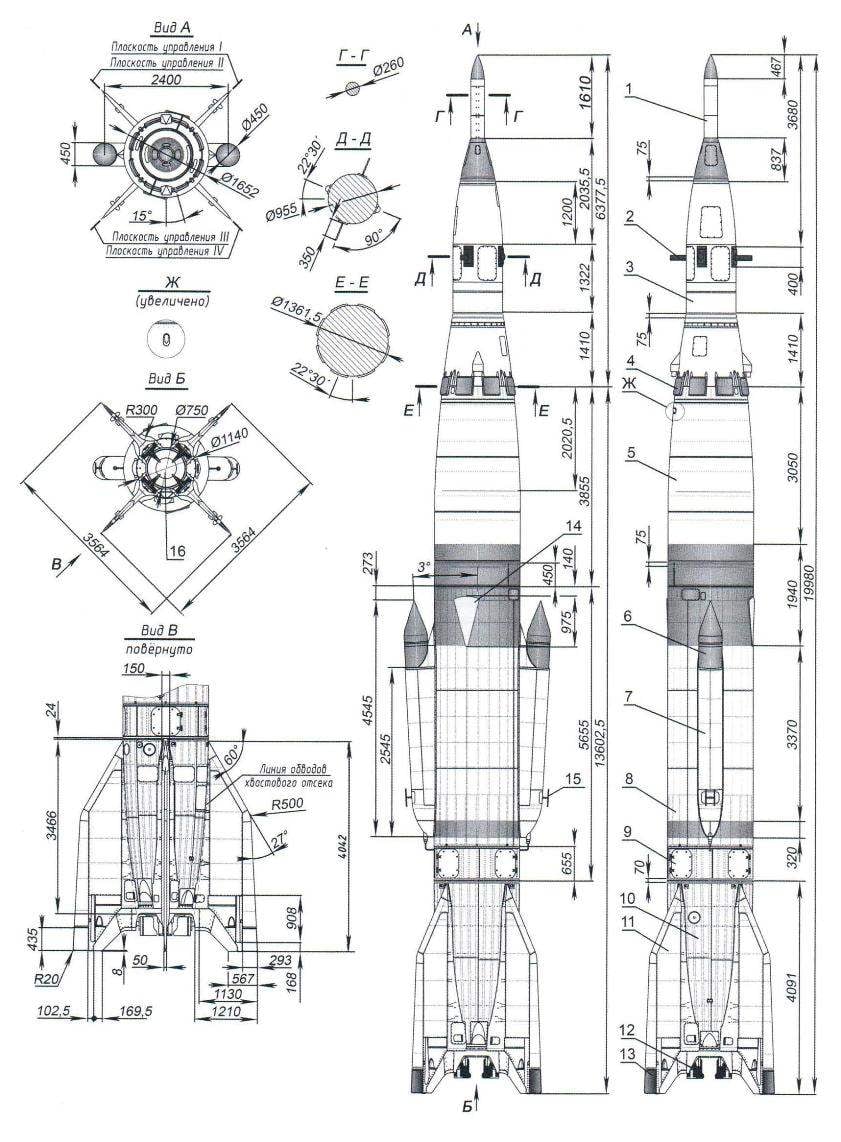
After the adoption in 1952 of a ballistic long-range missiles (R-2) necessitated the study of the atmosphere at altitudes above 200 km. Apparently, at the time and was tasked with creating and launching of artificial Earth satellites. It was then, in 1954, on the basis of the R-2 and began to develop a geophysical rocket R-2A. The basis for its creation took technical solutions used for test firing in the first modifications of R-1 and R-1E. So, for the R-2A designed a new head part with a mass of about 1400 kg – sealed compartment for studies of animals that were saved together with the head part.
 
Deceleration of the head portion produced by the opening of the brake flaps. At its further decrease sequentially was introduced three exhaust chute, and at 1600 -2500 meters revealed two main parachute.
 
The payload is housed in the head part and the two side containers, fire back pneumatic mortars at an altitude of about 65 km. the Head part was separated at the altitude of 195 km, includes a sealed cabin for the dog, camera and scientific equipment.
 
Sequence diagram of the missile R-2A is as follows: start – 0, ejection side containers (67 km) – 103 C, the separation of the head portion (at an altitude of 195 km) – 188 with the opening of parachutes at WARHEAD and shoot containers (altitude 5 km), the time from start – 400 p
 
From 1957 to 1960 there have been 13 launches of geophysical rockets R-2A, 11 of them successful.
 
Tracing the idea of their creation, will not escape from our attention and some pattern in the technology of their construction on the example of case diameter rockets. He first -1652 mm. It is apparently allowed then to use the technological mandrel, dies for manufacturing large series of missiles. To ensure a rational approach to the creation of the then new technology.
 
Model-a copy of the R-2A made in scale 1:25. It should be noted that the selected scale allows you to use a previously manufactured mandrel for a large series of models first domestic missiles.
 
In our circle model was built in two versions. For beginners the copyists – no shooting, and prepared, with a branch in flight layouts side mortars.
 
The first step in creating any copy -selection documentation – drawings and photographs. I must say that today its a lot – you just have to look.
 
Practical work can begin with the manufacture of elements of the case. The Central body (cylindrical) are glued together on a mandrel with a diameter of 65 mm and two layers of construction paper with a thickness of 0.2-0.25 mm.
 
After drying the resulting workpiece treated (sanded joint) emery paper and coated with a single layer of nitro lacquer. Then paste it on the one layer of paper, after making the workpiece markings riveted joints with knurled – cog from the clock with a diameter of 30 mm. After drying, the surface is cleaned with fine emery paper and cover with two layers of nitrocellulose lacquer. I want to note that all of these technological operations are performed on the mandrel. Giving to dry the workpiece, it is clamped in the Chuck of the lathe and on small speed (150 – 170 rpm) butt to the desired size is 284 mm.
 
The elements of the arched form is the nose and tail is glued on the respective mandrels by means of papier-mache. The mandrel with the pre-heated and grease separation with mastic. The label of the “petals” are the clay “the Carpenter”, and before that they must be wet for a better fit to each other, the shape of the mandrel. On one layer you will need eight or nine “petals” – width 20 – 22 mm. And just have to stick to seven or eight layers.
After drying, the obtained workpieces are processed with a file to remove bumps. Further, each clamped in the Chuck of the lathe and centruum. At low speed (about 70 – 100 rpm) ostrozatochennym cutter process the billet to the desired size and vasculat. If there is roughness, putty and re-treated. Then cover nitrovarnish, mark the location of the riveted joints and rolled (the gear of the clock in increments of 1.2 – 1.5 mm) they mimic. To use gear with smaller increments does not make sense. Further painting parts of these seams will become numb paint and the desired effect is not achieved.
 
Allowing the paint to dry, butt the workpiece to the desired size – the bottom – up Crimea will receive 134.6 mm length, top – up to 152 mm. After this operation, the workpiece is heated slightly and holding the mandrel in the machine, remove them with the details.
 
Fairing with a length of 140 mm carved from basswood on a lathe, easy in and cover with two layers of nitrocellulose lacquer. In its upper part glued tip, length 70 mm, made of birch, and the bottom (wide) part of face piercing holes, the “skirt” width 5 – 6 mm through which glued the Radome in the nose (augy-shaft) part of the body. Bottom fixed connecting boss, made of basswood with an outer bore diameter of 59 mm. In a lug glued end cap with fixed loop of sturdy thread for suspension of the parachute.
 
The connection of the Central body and tail of the element takes place in that order. First glued two layers of paper “Delineator” up-ognevoj length 135 mm and fix it three the frame. Two of them are made of balsa, and the third power – carved out of Linden. Assembled power unit (agnesod with frames) glued in the rear element. Then it’s the same insert and fix here connecting sleeve which pushed the Central building. The other (free) end of the Central housing sleeve is also glued 25 mm wide for mounting the nose of the model.
 
Geophysical rocket R-2A
Geophysical rocket R-2A:
 
1 – ballistic tip; 2 – telemetry antenna head part; 3 – warhead; 4 – the brake pads; 5 – fuel tank; 6 – shoot the instrument container (mortar); 7 – the body of the container;
8 – cell; 9 – instrument compartment; 10 – tail section; 11 – bracket for the stabilizer; 12 – gas drive; 13 – aerodynamic handlebars; 14 – antenna of the frequency control; 15 – telemetry antenna; 16 – nozzle GGRD-101
 
Model-a copy of the R-2A (scale 1:25)

Model-a copy of the R-2A (scale 1:25):
 
1 – tip; 2 – heat shield; 3 – brake pads; 4 – connecting lug; 5 – connecting bushing; 6 – cap; 7 – loop parachute suspension; 8 – strand suspension parachute (recovery system); 9 – chute head portion; 10 – body; 11 – the parachute housing; 12 – wad; 13 – upper frame; 14 – connecting sleeve; 15 – a tube (container MRD); 16 – the rear compartment; 17 frame; 18 – steering wheel control; 19 – power frame; 20 – mrad; 21 control; 22 – fairing mortars; 23 – body; 24 – container; 25 – frame; 26 – a spring ejection mortars; 27 – pin; 28 – tail fairing of the container

 
Mandrel for the manufacture of model elements-copies of the R-2A
Mandrel for the manufacture of model elements-copies of the R-2A:
 
I – for the bow; II – for housing; III tail section IV – housing side of the container

 
Stabilizers, four of them, cut from the balsa veneer with a thickness of 4-5 mm, the edges around the fake slats of the same thickness. After that, three adhesive points connect to the package and processed using a loop. The packet is then disassembled, the profile of each stabilizer, paste over writing paper with printed markings riveted seams, and coated with nitrocellulose lacquer. Processing the convex side, adjust each stabilizer to the tail compartment. The attachment strengthens the paper strips, mimicking the fairings of the rocket prototype.
 
Body side containers vyklevyvajut the notched mandrel of two layers of drawing paper. After drying cut them in the shape of the side view; from the inside, from the bottom keut plate of balsa, 5 mm thick, and rear – boss, giving it the desired shape. On the bottom surface of the container make the groove for a tight fit to the body and glue in place to the main building.
 
The discharge of the mortars, a cylindrical tube of paper with end terminations of lime. On the lower end of each of the mortars pinned the pin of bamboo with a diameter of 5 mm and a length of 30 mm. it is attached the spring for shooting.
 
After assembling the whole model conduct a “filling” of the outer surface of outer elements (manholes, pads, etc.), and inside threads attach (halyards) to connect the parts of the copy with recovery system – parachutes. In this model there are two. Single – diameter 350 mm -for the salvation of the head portion, the second diameter 500 mm – main body.
 
Assembled model lightly sand. If there are irregularities, roughness is eliminated. Paint the model according to the available documentation (photographs).
 
Flight weight-models R-2A about 250 g. it Starts the engine MRD 10-10-3 with a special starting installation.
 
If the model is a copy of the R-2A demonstrates in-flight side of the mortars, then it is necessary to provide another powerhouse team (this may be of MRD-or MRD of 2.5-5). It is placed on the side of the Central. It has no lifting charge and it makes small holes (diameter 1-1.5 mm), in which the thread fixing mortars to start. The same holes are made in the body.
 
Model-a copy of this version will start with two engines, but while working the command MRD – 1,5 – 1,6 minutes. I want to note that the lateral placement of the motor command does not affect the trajectory model for low-thrust, moreover, the model has a sufficient area of the stabilizers. After the start command, the engine burns through the string that holds the mortar in the container, springs on the ends of the mortars “shoot” them out of the containers. They fly and after a moment open the brake band wrapped around their hulls. And the model on the main (host) the engine continues.
 
I must say that the implementation of such a flight will have to conduct more testing of the flight cyclogram. Suggest this work is best done on a ballistic model.
Viktor ROZHKOV

Recommend to read

  • SPEED — up TO 120 km/hSPEED — up TO 120 km/h
    This model can easily produce young technician familiar with the basics of automodelisme and able to work on machine tools. The construction should start with the manufacture of the pan,...
  • WHEN THE TRAILER CAN NOT AFFORDWHEN THE TRAILER CAN NOT AFFORD
    Car trailer, about which speech will go, was produced by D. Baker. In General, still quite a young man — he is 25 years old. In their family, loving actively to spend the summer vacation...