Just the design of the engine made more than twenty all kinds of changes. The most difficult and time consuming was the installation of clutch and connection of the transmission to a flywheel housing of the engine. These problems were solved in the following way.
Instead of regular nuts of fastening of a flywheel installed new combination nut with pressed into her closed ball bearing, which is now part of the front end of the gearbox shaft.
The flywheel housing of the engine is enhanced by the so-called doubler, welded from sheet steel, the outer dimensions of which correspond to the internal dimensions of the casing. The doubler has a flange with threaded holes for the bolts securing the clutch housing from the GAZ-53. Flywheel housing with inserted therein a backup is attached to the crankcase with screws, the heads of which scontrini circle soft steel wire.
On the tractor installed tnodes – big deal grip from the GAZ-51. Due to the fact that the engine flywheel is hollow, the clutch cover had to be fixed to it via a special adapter — thick steel washer. I had to carve under it in the rear end of the flywheel of the landing recess with a diameter equal to the diameter of the casing of the clutch. For joint fixing washer, clutch casing and flywheel to the body of the last performed blind threaded holes for the screws.
When you install the clutch housing and mixed nuts of fastening of a flywheel I used the fixture for centering the axis of the shaft. (Description not cite, because it is not original. More or less experienced Amateur designers, tend to have device not worse.) Flywheel Assembly with clutch subjected to careful balancing.
TRANSFER BOX is suspended under the middle beam of the frame of the tractor on two special brackets that serve at the same time covers technological hatches Carter “transfer case”. The brackets are welded mainly of sheet steel of different thickness, and the holes attaching them to the box drilled. In addition, the right bracket has an axis for the lever for the PTO, at the transmission.
![Front axle]()
Front axle:
1 — axle shaft; 2 — a bolt; 3 — Cup; 4 — bearing 8207; 5,13 — washers-spacers (si); 6,8 — bearings 206; 7 — spacer; 9 — Cup washer (s2); 10 — rotary lever; 11 — a lock washer (s2); 12 — nut M20x1.5; 14 — beam balancer (pipe 80x80x6); 15 — the hinge of longitudinal steering rod; 16 — rotary lever (GAZ-51); 17 — bearing housing; 18,24 — rope suspension bridge (si6); 19 — axle suspension Assembly of the axle; 20 — press Maelen-ka (size # 1); 21.27 — bearings 2206; 22 — the rib (s5); 23 — cross beam of the frame; 25 — pin; 26 — castellated nut M20x1,5.
Mount the wing above the wheel peredney bridge:
1 — wheel; 2 — the balance wheel of the front axle; 3 — bracket to the swivel arm; 4 — bolt MU (2); 5 — wing
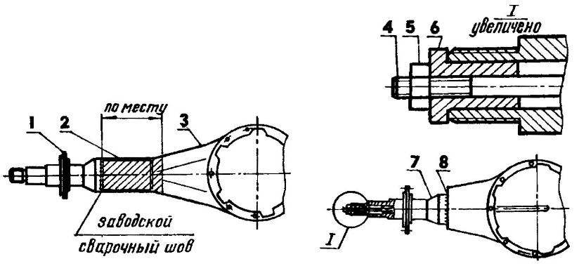
Scheme revision rear axle:
1 — flange of the axle casing; 2 — remove part of the axle housing; 3 — Karger: 4 — pin coupling M20x1,5; 5 — nut M20x1,5; 6 — guide Bush: 7 — stub axle housing; 8 — new weld
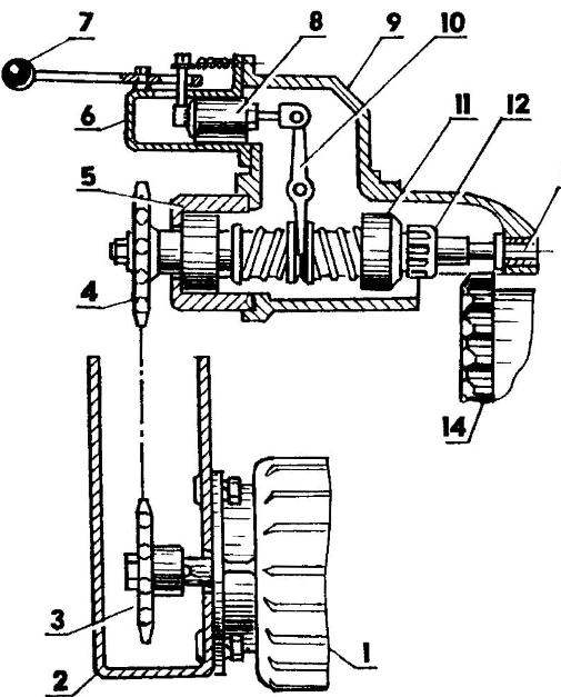
The scheme starter:
1 —three — phase asynchronous motor; 2- bracket-cover; 3,4 — leading and conducted final drive sprocket (z = 18, t = 19,05); 5 — head of a starting device; 6 — the case of the switch of the starting device; 7 — the lever of the switch; 8 — pusher; 9 — body of the starter; 10 — the lever-yoke; 11: clutch; 12 — a pinion gear of the starter; 13 — shank composite cushion; 14 — a gear wreath of a flywheel of the engine
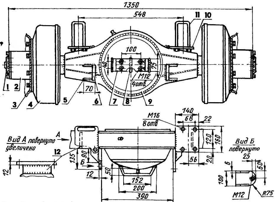
Rear axle (rear view):
1 — axle flange; 2 — hub; 3 — drive wheel (the tire is conventionally not shown); 4 — drum; 5 — square scarf (steel, sheet s6,4 PCs); 6 — hinge to frame attachment device (the steel sheet s 12, 2 pieces); 7 — bracket towing hook (steel, sheet si2); 8,12 — props (steel, sheet s12, 3 units): 9 — Carter; 10 — supporting base for the frame of the tractor (steel, the sheet s 12,2 PCs); 11 — the ladder mounts to the frame Ml6x1,5 (4 PCs)
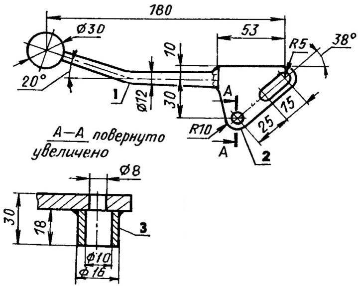
Main switch starter (and — in the assembled state, b — in parts):
1 — body switch; 2 — the lever of the switch; 3 — nut M8; 4 — finger Ml0; 5 — return spring; 6 — hook; 7 — a bolt, IB (3 units); 8 — the body of the starter (starter cover, ST-15); 9 — weld-nut M10; 10 — pusher (anchor of the traction relay of a starter ST-15)
Case switch:
1 — glass; 2 — the axis of the lever; 3 — a flange (starter ST-15); 4 console
Lever switch:
1 — crank; 2 — sector 3 — sleeve
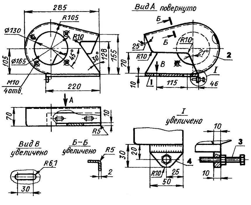
Bracket-chain box:
1 —Playground (strip 50×10); 2 — a casing (sheet si0. s2); 3 — M8 bolt chain tension; 4 — bracket
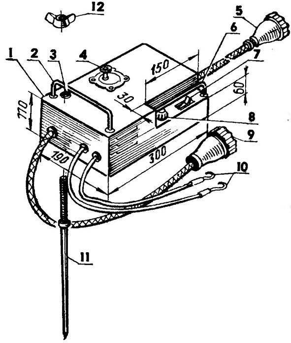
Remote engine start:
1 — housing (sheet s2); 2 — carrying handle (rod 05); 3 — through the slot under the pin protection function-‘ tion; 4 — leg button switch (COP-31M); 5 — connector output cable; 6 — protective ring (rod 05); 7 — automatic AB-25M; 8 — signal lamp; 9 — input connector cable; 10 — conductors power glow plugs: 11 —ground pin (rod 012, L300); 12 — nut-lamb M12
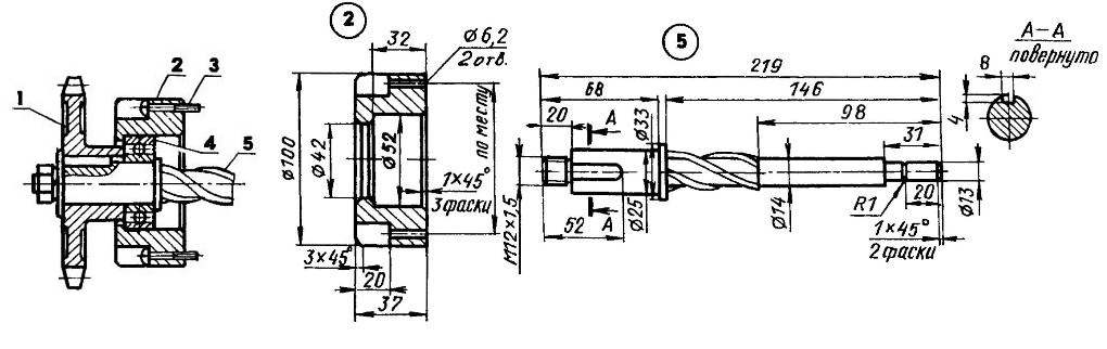
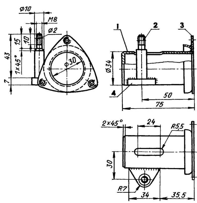
Head starting device:
1 — sprocket driven (z = 18, t = 19,05); 2 — glass; 3 — screw MB (2); 4 — bearing 60205; 5 — part cushion (litsevoi part of the rotor of the starter motor SG-15)
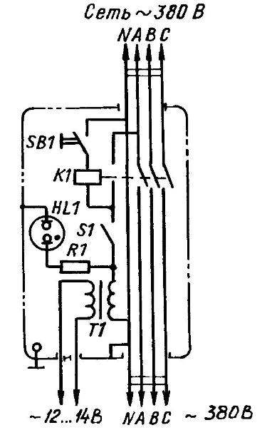
Schematic diagram of the remote control engine start
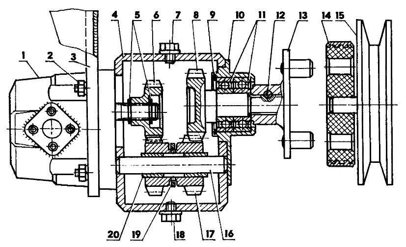
The hydraulic pump:
1 — hydraulic pump NSH-10; 2 — nut M8 fixing water pump (4 PCs); 3 — bracket; 4 — a gear unit actuator; 5,9 — retaining rings; 6 — driven gear; 7,18 — tube filler and drain holes; 8 — pinion gear with splined shaft; 10 — cover the crankcase with a bearing housing; 11 bearings; 12 — bolt; 13 — a plug half coupling with two pins; 14 — rezinometallika-Kai coupler; 15 — drive pulley (d140); 16 — the axis of the block of intermediate gears; 17 — the block of intermediate gears; 19 — roll switch; 20 — figure bronze bushing
The device has a mechanical switch operated pump:
1 — the gear unit drive; 2,3,4 — screw, spring and ball retainer; 5 — the case of the mechanical switch; 6 — sector switch; 7 — head switch; 8 — a sealing washer; 9 — gasket; 10 — a pin-guide plug switch; 11 — leash switch; 12 — the plug of the switch
The main body gear components drive the hydraulic pump:
1 — gear housing (138x120x89, the sheet s8); 2 — stud M8 housing mounting the hydraulic pump (4 pieces); 3,11 — tube filler and drain holes (screws M12); 4 — cover the crankcase with a bearing housing; 5 — M5 screw (9 PCs. ); 6 — socket retainer; 7,10 — dowel pins (d6); 8 — the case of the mechanical switch (sheet s6); 9 — M6 screws (2 PCs.)
FRONT AXLE — wheels from UAZ. Balancer axle is made of steel tube section 80x80x6 mm long, the ends of which with longitudinal and transverse slopes respectively 3° and 5° welded cups pivot bearings 206 and 8207. Two pairs of king pins and axle shafts machined separately, then connected by welding. The pivot bearing is lubricated through the grease fittings as needed (bearings of the wheel hubs — only before installing it on the axle).
In the suspension unit of the front axle used roller bearings 2206. This increasing complexity is due to the scarcity in our area bronze. However, destruction of these bearings even in the most severe conditions was not.
The hub and drives the front wheels of the car GAZ-69 Swivel arms improvised, forged, with subsequent machining and metal processing. The camber is constant (2°), incorporated in the design of the front axle. Convergence is governed by their shortened tie rod from the GAZ-51.
The FRONT WINGS are homemade, with rubber mud flaps. Back — factory made tractor T-20 but with a partially changed the mounting brackets.
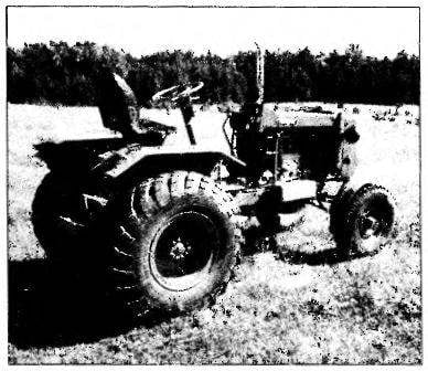
REAR AXLE of the car GAZ-53 (with shortened housings axle shafts). Wheels — ZIL-157 as the most suitable for the operating conditions of the tractor. Main gear — from GAZ-66, as its Cam limited slip differential eliminates slippage one of the wheels that increases the permeability “of Angara” for damp, sand and arable soil. To the frame of the tractor rear axle attached ladders.
Alteration of the bridge (shortening the rod casings) made at home. The process sequence was as follows.
From Carter bridge, I drained the oil. Dismantled the axle, the hub and main gear. From the factory the welds connecting the axle with cover measured to the center of the length of the deleted sections. Line cutting firebreaks along the perimeter superchanel and arable soils.
To the frame of the tractor rear axle attached ladders.
Alteration of the bridge (shortening the rod casings) made at home. The process sequence was as follows.
From Carter bridge, I drained the oil. Dismantled the axle, the hub and main gear. From the factory the welds connecting the axle with cover measured to the center of the length of the deleted sections. Line cutting firebreaks along the perimeter of the storage-
bill to a depth of 1-2 mm, to better see them in the blinding light of the gas torch. And gently separated first axle, and then shortened the shrouds.
After complete cooling cleaned the place from cutting slag. Missed through the crankcase long stud, for all put it on the axle with the guides and gently tightened the nut. Tapping the axles hammer plumbing, installed them in the middle section casings, controlling the size of the caliper. Tightened the nut to the end of the first tack, and then multi-pass and symmetric welding seams (to reduce warpage of the structure) was finally connected with the axle housings.
Pinch the pin with guide bushings dismantled after the complete cooling of the metal.
Thick and rigid walls of a crankcase of the rear bridge allowed me to place any additional equipment in the form welded to the brackets, support pads and loops.
BRAKES. The tractor is equipped with two braking systems: a hydraulic working acting on rear wheels, and a mechanical handbrake operating on the transmission (transfer case). The first brake system — entirely from GAZ-53, second from GAZ-51.
THE TRIGGER SYSTEM OF THE ENGINE. Unfortunately, diesel engine, mounted on “Angara”, has a difficult start. It takes time for preheating the spark plug even at positive temperature of air on the periodicity of the starter and so on. Therefore, the use of standard electric starter ST-15 and warm candles require this engine battery with a capacity of not less than 75-180 Ah.
Buy a battery I was expensive, and I chose a different, unconventional way of starting the engine — with the use of asynchronous three-phase motor power 1,5 kW (at 2850 rpm) power supply 380 V Mounted together with bracket-casing left on the frame of the tractor, it through a chain transmission with a gear ratio of I = 1 rotates the composite cushion pad of the device, and that, in turn, the flywheel of the engine crankshaft.
The starter consists of housing (front cover starter ST-15); head (of a glass bearing 60205 and an integral cushion on which you sit, the driven sprocket, clutch, starter gear, thrust washer and bronze bushing bearing); switch with a lever and a pusher (anchor of the traction relay of a starter ST-15); arm rocker.
Engine “Angara” starting system installed on the place of the regular starter.
The engine is started in the following way. The socket electrical connector on the frame of the tractor, I connect the cable plug from the special remote control, and wire the circuit warming up the candles — to the terminals of the electrical shield on the tractor. Only after that connect power cable control panel with power supply of 380 V.
On the remote triggered automatic switch and light bulb circuit warm-up candles. On the engine is ready to start judging by the control element on slack-troxide, the intensity of which indicates the degree of heating of candles.
By hand turn the lever of the switch, and enter the starter gear fully engages with the ring gear of the flywheel on the crankshaft of the engine, and leg press the button on the remote control and switching on the motor. As a rule, a good warm candles the engine starts immediately. Then I unplug the console from the mains.
So as to power the starter motor used life-threatening stress, I have taken all the necessary safety precautions. Namely, the power to the panel is via a circuit breaker of the series A-3100; a power transformer through the circuit breaker of series AB-25M; all connecting cables are four-wire in a metal braid; the tractor’s chassis, remote control, motor and cables are properly grounded.
When the engine of the tractor, standing on the open ground, the remote provides an additional device in the form of a removable ground pin. The pin is inserted into the socket of the panel, fixed by a wing nut and all the way stuck in the ground.
The control panel is welded from steel sheets 2 mm thick in a rectangular enclosure. It has a removable bottom cover, side ventilation louvers. Automatic inclusion of the power transformer and the signal light bracket is protected from mechanical damages. Connecting cables and conductors insulated from the sides of the chassis by rubber bushings. Inside, a removable housing cover mounted machine AB-25M, power transformer TR-OSO-0,25, and magnetic starter, PME-211.
The magnetic circuit of the transformer additionally is wound 16 turns of insulated copper wire 14 mm2. Remove them with a variable voltage of 12 V serves as a power electrical circuit of the heating candles.
Of course, the method of starting the engine is quite complicated, but for me it was a way out. Now, when on the “Angara” installed everything needed for normal operation of the tractor electrical equipment, you can easily go to the start using the starter. And the mounting bracket of the starter motor to use to install the platform under the battery.
A HYDRAULIC SYSTEM. Tractor mounted hydraulic system designed to control the driver’s workplace all mounted and semi-mounted implements. It includes the valve, gear pump HLU-10, power cylinder, oil tank, piping low and high pressure valves
The hydraulic pump with the actuator attached to the crankcase timing gears of the engine through a homemade reducer that increases the nominal speed of the pump 1.2 times. Drive allows you to turn on the pump with one hand.
Gear drive used slightly modified gears and shafts from the transmission of the motorcycle “IZH-56”. In the case of a reducer welded from galvanized sheet steel, filled with gear oil TAP-15V.
The valve R75-23 three-piece. Constantly working on one section, the other two only when mounting additional equipment.
The hydraulic power cylinder from the combine harvester. Cylinder rod with adjustable forks and the finger is connected with the pivoting arm of the hinged device.
Oil tank is structurally designed at the same time with the right Polikom that four bolts M10 attached to the respective brackets on the frame of the tractor. For reliable operation of the hydraulic system all input and output connections of the tank are provided with filters.
V. PETROV, Krasnoyarsk Krai
Recommend to read
 LIFEGUARD SUBMERSIBLE PUMPS
In the process of exploitation of the deep (submersible) pumps often break. To catch them on the outside of the flange for lifting from the well is impossible due to the tight fit of the... RESCUE CLIP
How to be if urgently need to carry out drafting work using ink, a special ruler with a raised above the paper edge among the tools was not there! A way out of this situation is shown in...