SIZE ADAPTER “CROWN”

SIZE ADAPTER

When you turn on the power source smoothing capacitor C1 is gradually charged via the resistor R4, serves to protect the diode bridge VD1 overload. There is a voltage at the output of the trigger divider. Due to the fact that it affects the resonant circuit, consisting of transformer T1 and capacitor C2 in the secondary winding II is induced EMF from the pulse, the power of which is sufficient to switch the transistor VT1 is in the saturation state, although the initial moment of time the current through this semiconductor triode is not due to the self-inductance of T1. Then starts to do the “addition” from the winding II, holding VT1 is in the fully open position.
The VT2 transistor during the half cycle of the oscillatory process is fully locked. It holds in this state, the EMF that is induced in the winding III. But after the charge of the capacitor C2 the current through VT1 stops and it closes.
 
However, the oscillatory process in the circuit T1C2 does not end there. The result is current. Originating at the beginning of the second period (when the transistors are in the closed state), it will flow through the second arm of the trigger divider, which consists of parallel connected to R6 and the emitter-collector conduction VT2.
 
Similarly considered phase opens the VT2 transistor and held in the fully open position. However, after the discharge of the capacitor C2, the transistor VT2 is closed.
 
The transistors operate with minimal losses of energy in the most advantageous key mode. The current flowing through them, the entire specified bandwidth of the oscillating circuit.
 
Thus, a device and there is nothing like economical attenuator (attenuator) the current passing through the load. Output energy is removed from circuit the windings IV and V. the high Frequency oscillations are straightened diodes VD2, VD3, and a smoothing capacitor CP. The output of the Zener diode VD4, in parallel to which can be connected load up to 40 mA. With more tokoeka consumers increased low frequency ripple and reduced output voltage.
 
As shown by years of exploitation, this adapter does not fail in different situations, until the closed-loop output buses with the extreme 200 mA. Due to the resonant properties of the oscillating circuit is a partial smoothing of the low-frequency ripple at low load (the smaller, the higher is the smoothing). However, the quality factor drops sharply when the voltage at the ends of the windings IV and V exceeds the voltage on the capacitor of Sz, since the contour is given energy.
 
The high q of the circuit, occurring in the absence of selection from it of energy, leads to the achievement of equal voltages. This occurs due to a resonance even at a lower value pulsing Ubx. But further growth of the voltage on the resonant circuit does not occur due to the sharp fall of the quality factor caused by the energy extraction.
 
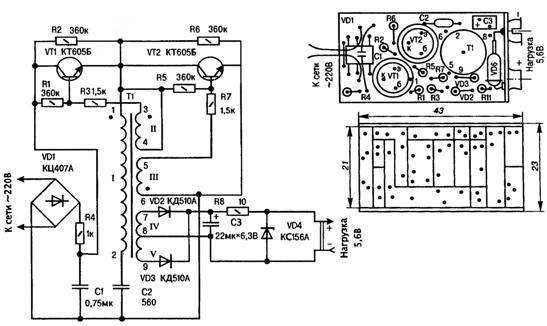
Now about the parts and components of the adapter design. Transformer T1 is made on a ferrite ring К10х6х5 1000НН. Windings I, II, III, IV, V contain, respectively, 400, 30, 30, 20 and 20 turns of wire PELCO-0,07. The high reliability of this transformer guarantees high-quality production with good PVC winding insulation (for example, using a condenser or tissue paper).
As much as possible, reduce the size, it is desirable to use the adapter ultraminiature capacitors overseas production. This is particularly advantageous in relation to C1. If required bolsaescola “tnik” at hand do not prove, that will have to be content with a relatively compact battery from domestic small-sized capacitors with a more common parameters (for example, five parallel KM-5 Н90 with a capacity of 0.15 microfarads each). Although the nominal reference voltage the representatives of the group Н90 equal to 50, the majority of them stand +Usup coming from the rectifier bridge through a resistor R4. Besides, the scheme itself does not allow any serious consequences of the breakdown of these capacitors, for R4 works here as a kind of fuse.
 
If the size of the design of the adapter is not critical, as a C1 you can use any of the domestic high-voltage counterparts. And the greater the capacity, the better the aliasing of low-frequency pulsations.
 
Capacitor C2 is of type KM-4 (560 pF, 300 V) or the like. When you choose NW you can stay on K53-16, although other small domestic manufacturers with electrical parameters not lower than indicated in the diagram. All the resistors type C2-23, MLT but perfectly acceptable and they are not less common anapoli. The size and magnetic permeability of the ring magnetic core of the transformer T1 may also be slightly different from those ispolzovany in the original adapter.
 
Obvesti applications are considered improvised explosive devices can be substantially expanded, using in its design of more powerful transistors, for example, КТ809, КТ812, КТ859. You will have to adjust the parameters of the resonant circuit, increasing the capacitance C2 and a transformer wound on a ferrite ring a few more sections. Do not then without careful selection of the resistances of the resistors R1, R3 and R5, R7, to provide powerful transistors base current.
 
With the estimated 50 mA consumption with a standard load, the operating frequency of the energy transformations in the adapter of the order of 100 kHz. This cannot be dismissed as ignoring the possibility of abrupt reduction in the inductance of the oscillating circuit (and hence the dimensions of the transformer, which inevitably entails a reduction in the size of the entire card as a whole) through the use of transistors with higher f
Installation is carried out on pseudospectral Board with 1.5 mm foil Micarta or textolite. The conductive elements are get, cutting the foil with the subsequent removal of all the excess. The tool is sharpened in a special way bench knife or a cutter from a piece of cloth from a hacksaw on metal.
 
Transistors mounted on Board with a small excess of one over the other, except touch their shells under different potentials during operation. Next mount the transformer by putting it on a pin soldered thick copper wire in vinyl insulation. Pin 1 and 4 of the windings I and II passed through the specified hole in the circuit Board with the subsequent sealing of the corresponding “printed” conductor.
 
The capacitor C1 is mounted over the rectifier bridge VD1 type КЦ407А. Resistors and diodes VD2, VD3 soldered to the Board vertically. To the input end of the circuit Board attached (with solder-in bracket) wire to connect the adapter to 220 V. On the opposite — placing the output socket, primaeva it to the pins of the Zener diode, there are pre-installed in a horizontal position. Almost ready adapter wrap a condenser paper or a thin plastic film and placed in a metal casing from a small battery “Crown” shaped contacts which are in this case
 
as the socket-pin connector for connection to the load — equipment that is used on digital circuits.
 
On the same principle you can create and powerful power sources, up to ultra-compact welding machine.
 
Electrical schematic and a printed circuit Board, miniature voltage Converter household power 220V To DC 5V-voltio — to power a low power apparatus, insensitive to interference
A circuit diagram and a printed circuit Board, miniature voltage Converter household power 220V To DC 5V-voltio — to power a low power apparatus, insensitive to RF interference
 

Adapter assembled in strict accordance with circuit and installation diagrams from a known good radiotherapy, in particular from-Phadke as previo, needs. Napadenii sometimes spiny heating of the transistors is the proof of their neparnogo opening when working in kucevo mode — eliminate the selection of resistors R3, R7 and proportional to the adjustment of the values of the resistors R1, R5. If you want different than shown in the diagram, the output voltage, it poluchaut changing the number of turns in the windings IV and V of the transformer and replacement of the Zener diode КС156А another, more appropriate type. But to the simultaneous existence of multiple output voltages using a chain of Zener diodes connected in series.
 
In the operation of any of the options of this adapter should observe the well known precautions to avoid injuries by electric current domestic network.
SOLONIN, G. K o n o t o n, Sumy region, Ukraine

Recommend to read

  • WELDING MACHINE FROM LATERWELDING MACHINE FROM LATER
    Sure: from a compact and yet sufficiently reliable, cheap and simple to manufacture "svarochnik" no workman, Thrifty, the owner will not refuse. Especially if he knew that at the heart of...
  • “CLOTHESPIN” FOR METAL“CLOTHESPIN” FOR METAL
    One of the major examination quality, which is a metal or alloy before you can become a responsible part of modern technology, the test of a test sample in tension. However, to determine...