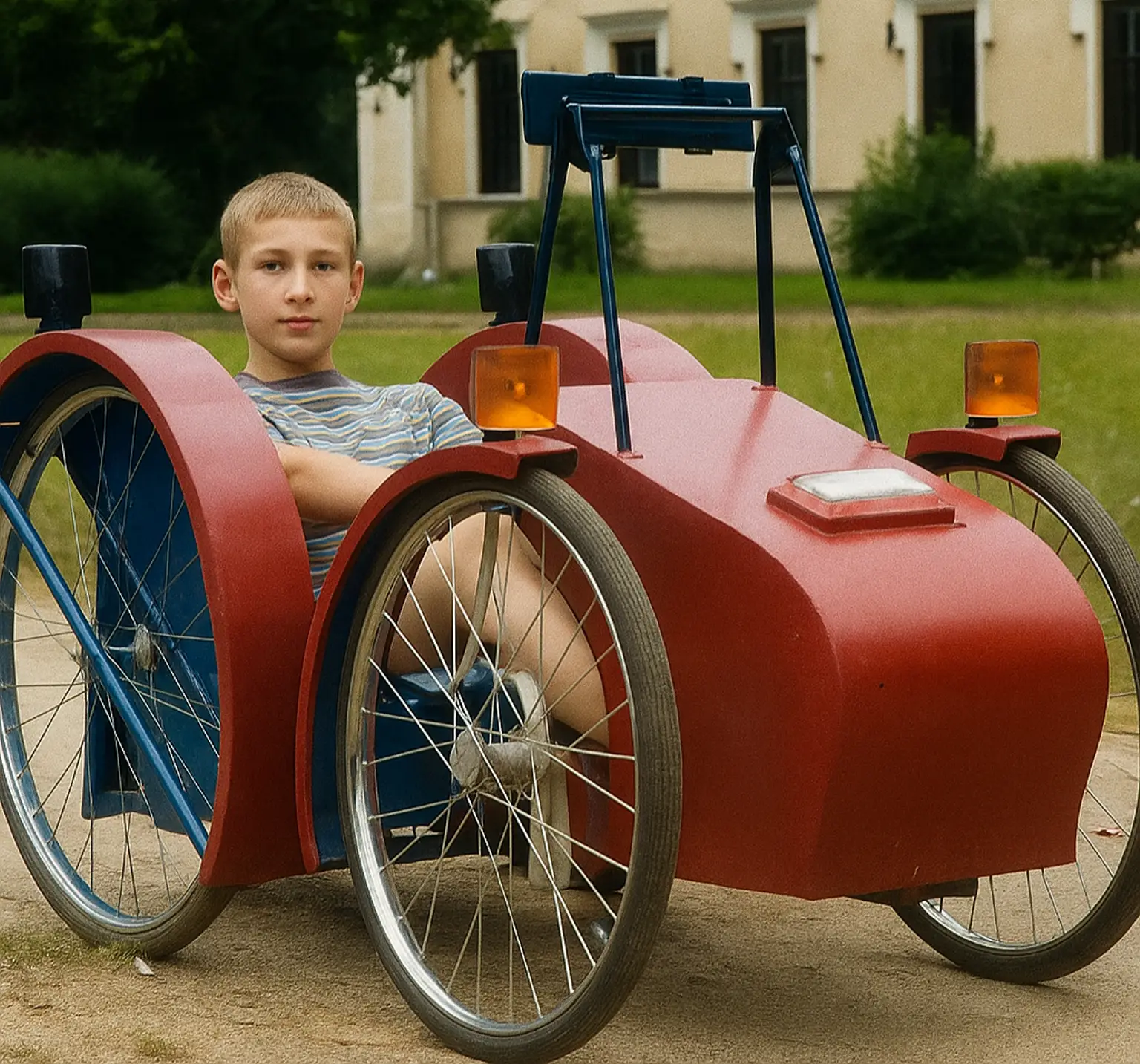
The idea of creating a small four-wheeled carriage with an electric drive for pleasure trips around the picturesque surroundings of Peterhof came to us last year.
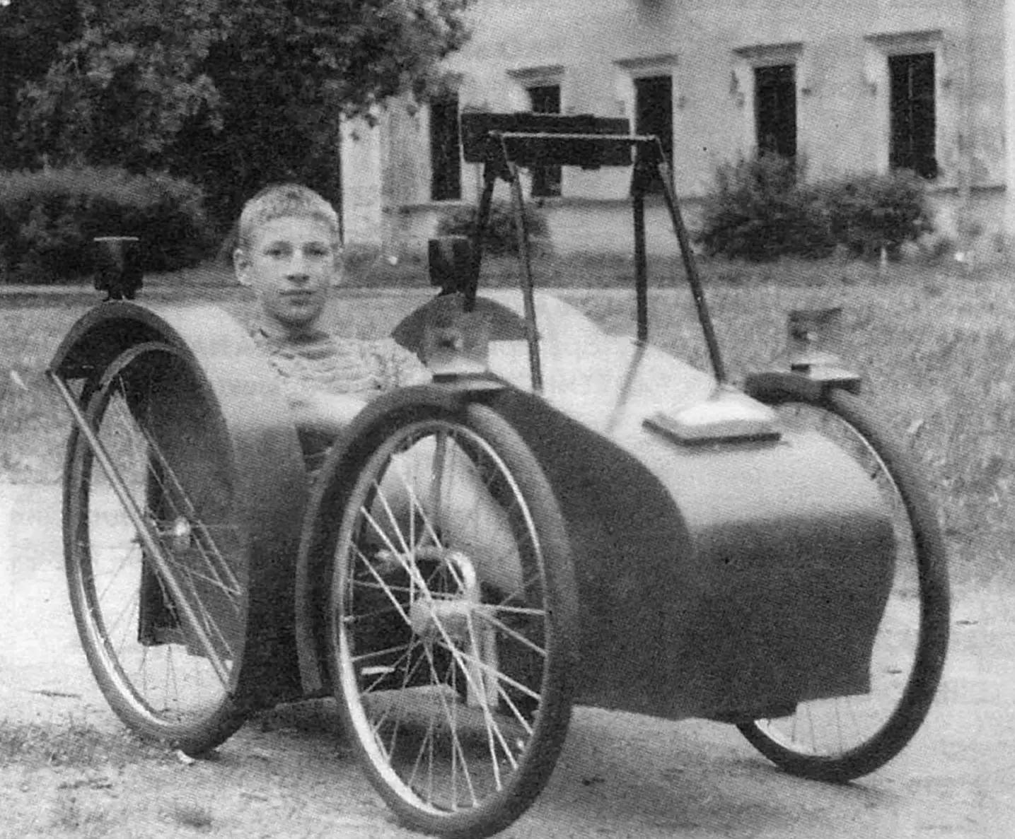
Before that, we built a two-wheeled vehicle that was driven by an electric drill, powered by a car battery through a transistor voltage converter.
But the vehicle was difficult to keep balanced at low speeds and with frequent stops, as it carried a battery comparable in weight to the chassis itself.
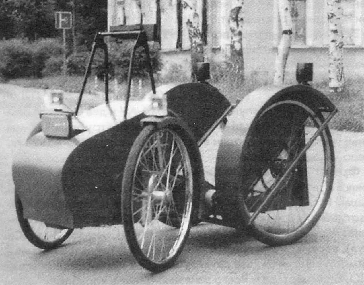
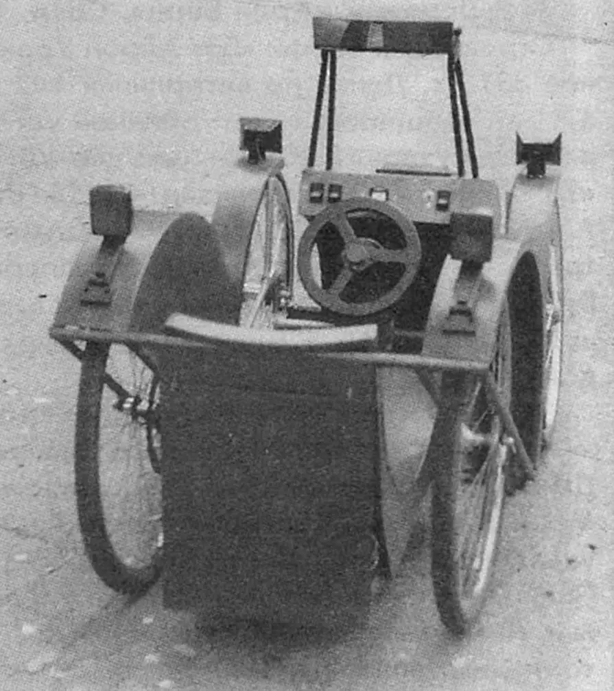
We made the new electric car, called “Debut”, in three months, not counting the preparatory period – working out the design, preparing materials, mechanisms, and parts.
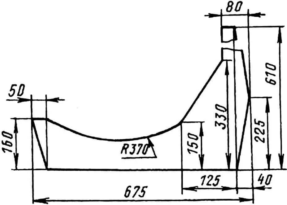
The main element of the chassis is a simple frame made of pine boards 1550 mm long and 110 x 23 mm in cross-section. It unites the front and rear parts of the car. In the rear part, a subframe is mounted, welded mainly from half-inch water pipes in the shape of a hut. This shape was chosen for a reason: with a minimum number of parts, the subframe has the greatest rigidity. And this is necessary for it, because it acts as a rear axle and bears the main load from massive batteries and the driver.
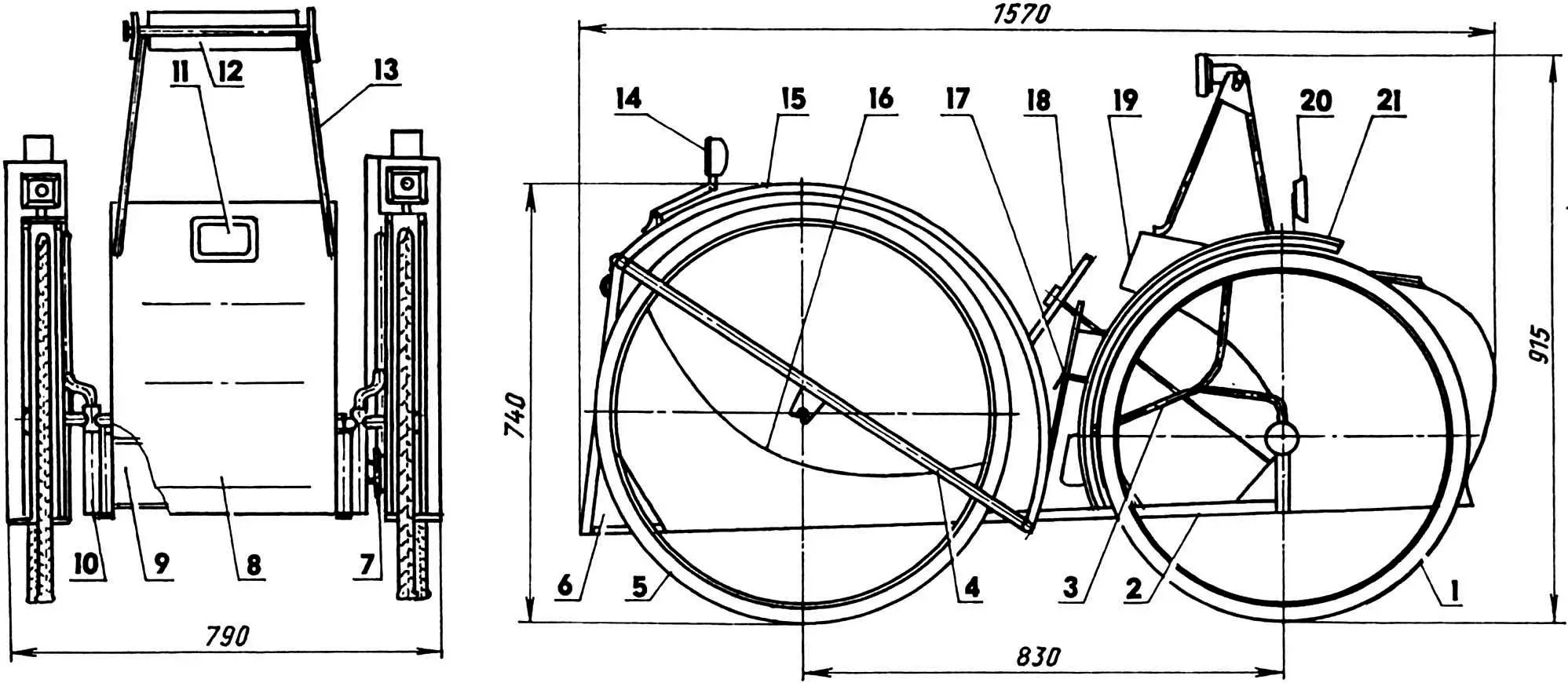
1 — front swivel wheel (bicycle 37-533); 2 — frame (board 110×23, L1550); 3 — front fender mount bracket (duralumin pipe 22×2); 4 — subframe; 5 — rear wheel (bicycle 40-622); 6 — battery compartment; 7 — drive sprocket (z = 6, t = 12.7); 8 — hood (hardboard, plywood s18); 9 — front axle; 10 — steering knuckle; 11 — retractable headlight; 12 — panoramic rear-view mirror; 13 — mirror post (steel pipe 17×2.2 pcs.); 14 — brake light (2 pcs.); 15 — rear fender (hardboard, plywood s18, 2 pcs.); 16 — seat (plywood s3 and s18); 17 — steering column; 18 — steering wheel; 19 — instrument panel; 20 — side light (galvanized sheet metal s0.5, 2 pcs.); 21 — front fender (hardboard, plywood s18, 2 pcs.)
The subframe is a welded assembly unit. It consists of six inclined pillars (two rear and two pairs of front) and three crossbars. All its parts, except for the rear crossbar, are made of half-inch steel water pipe. At the top, all the pillars are connected to each other by a common crossbar, while at the bottom, the front ones are connected by their own, and the rear ones are also connected by their own — made of a 40×40 mm angle bent from a 2 mm thick steel strip. In this case, the pairs of rear pillars are installed closer to the middle part of the crossbars, and the front ones are along their edges.
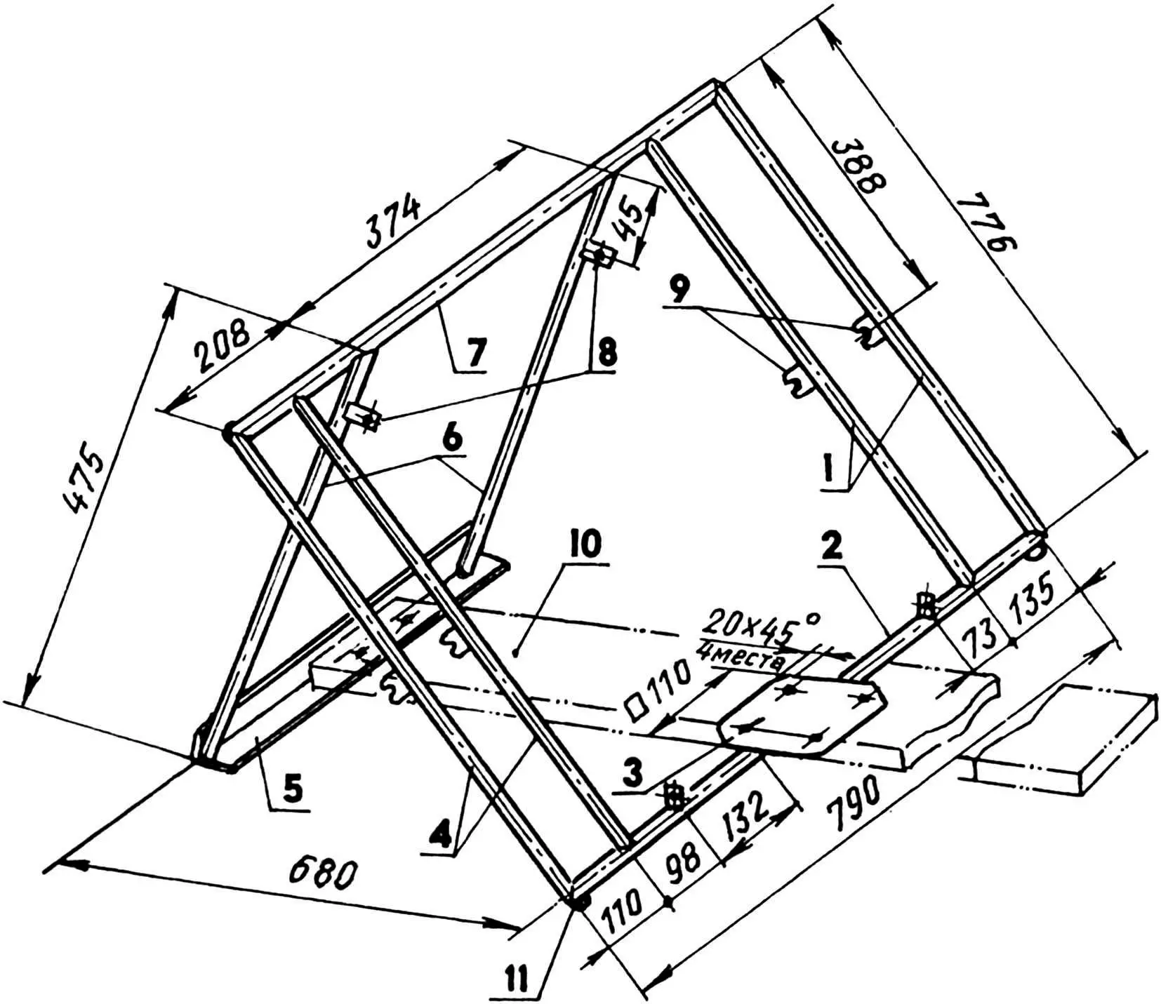
1 — left pair of front pillars; 2 — lower front crossmember; 3 — support (St3, sheet s2); 4 — right pair of front pillars; 5 — lower rear crossmember (angle 40×40, bent from steel strip s2); 6 — rear pair of pillars; 7 — upper crossmember; 8 — seat mounting brackets (St3, sheet s2, 4 pcs.); 9 — rear wheel axle lugs (St3, sheet s2, 4 pcs.); 10 — frame (board 110×23); 11 — ring for brake device pipe (wire Ø5, 2 pcs.); parts 1, 2, 4, 6, 7 are made of steel pipe 1/2″
The distance between the pairs of front posts is different, because between the left posts a rear bicycle wheel with a large driven sprocket and a brake hub is inserted. On the right side a wheel of the same diameter is inserted, but it has neither a hub nor a sprocket.
To mount the wheels in the subframe, each front pillar has lugs welded in the middle in the shape of bicycle fork tips. In addition, brackets with holes for attaching the seat to them are welded to the top of the rear pillars. Exactly the same brackets of the same width and for the same purpose are welded to the lower front crossbar. Also welded to it are: rings for the brake mechanism pipe at the bottom at the ends, and in the middle at the top is a support – a 2-mm steel plate with four 4-mm diameter holes for screws for fastening the frame board. Two holes for the same purpose are drilled in the horizontal shelf of the rear lower crossbar corner.
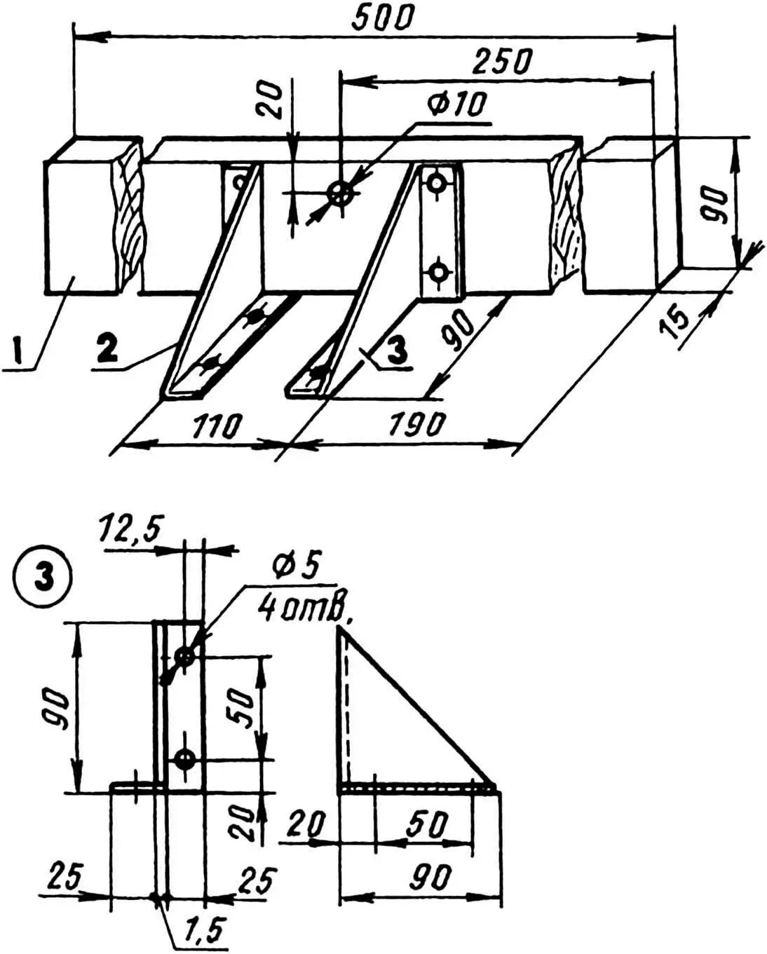
1 — beam (board 90×15, L500); 2 — left and right brackets (St3, sheet s2)
The front axle is mounted at the other end of the frame. It is also a section of a board with a cross-section of 90×15 mm and a length of 500 mm, installed on the edge across the frame. The intermediate connecting parts are two brackets, bent from a 2-mm steel sheet. Fastening is with screws. The homemade steering knuckles of the wheels are also attached with screws to the ends of the front axle.
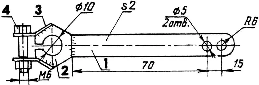
1 — lever (St3, strip 12×2); 2 — clamp (drilled nut M10); 3 — clamp antenna (St3, strip 8×2, 2 pcs.); 4 — bolt M6
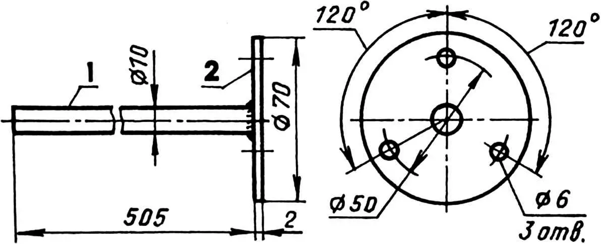
1 — shaft (steel rod Ø10); 2 — flange (St3, sheet s2)
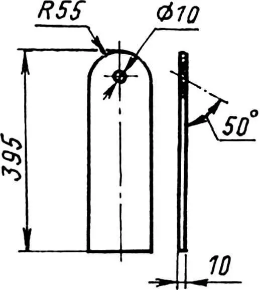
The crew is controlled by a drive consisting of a steering wheel, a shaft with a pitman arm, and a steering trapezoid. The wheel is cut from a plywood sheet 18 mm thick. It is attached to a flange at the upper end of the steering shaft. The pitman arm is mounted on its lower end using a clamp. The shaft itself (a steel rod with a diameter of 10 mm) is inserted into inclined holes in the column and front axle. The pitman arm and the left steering lever, as well as the levers (left and right) are connected to each other by wooden rods of the steering trapezoid.
The rear and front wheels of the chassis are different. The rear ones are 40-622 mm, the front ones (swivel) are 37-533 mm.
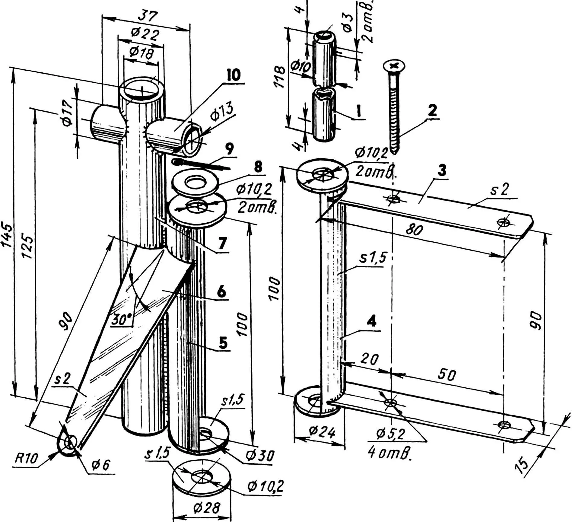
1 — kingpin (steel pipe Ø10); 2 — screw 5×50 (4 pcs.); 3 — bracket-cover (St3, sheet s2, 2 pcs.); 4 — inner kingpin half-bushing (St3, sheet s1.5); 5 — outer kingpin half-bushing (St3, sheet s1.5); 6 — lever (St3, sheet s2); 7 — rack (steel pipe 22×2); 8 — washer (2 pcs.); 9 — cotter pin (2 pcs.); 10 — wheel axle bushing (steel pipe 17×2)
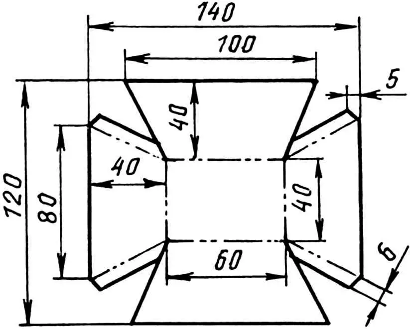
Engine and drive. A modified starter from an Oka car was used as an engine. All unnecessary parts were removed from it (up to the housing in which the anchor is located): the retractor relay, the overrunning clutch with a gear, etc., and a new front part was installed in their place – a homemade nozzle with an 80201 bearing. The shell of the nozzle is put on until it stops in the hoop on the starter housing and is “grabbed” to it with several welding spots.
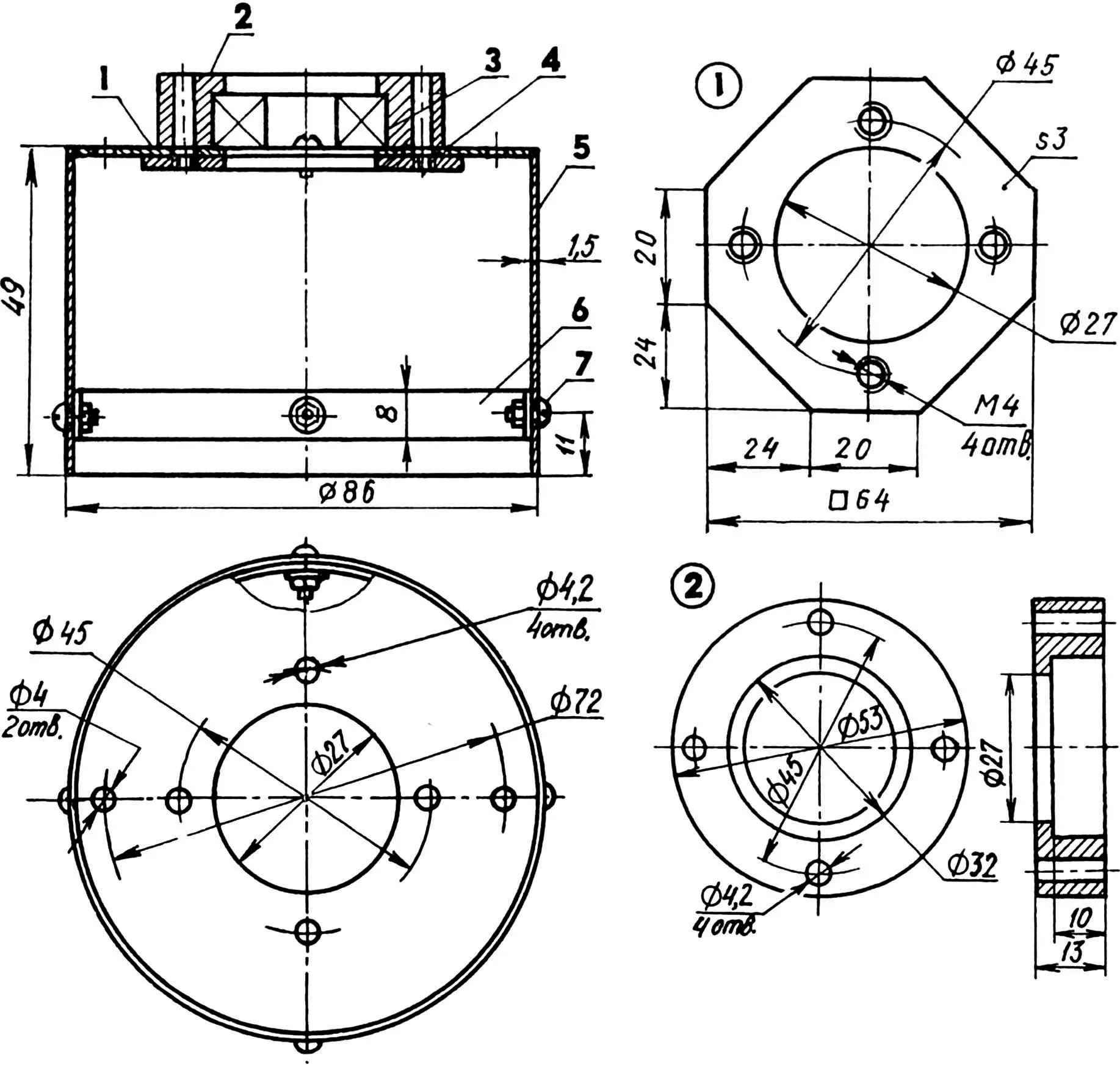
1 — lining (St3, sheet s3); 2 — cover (St3); 3 — bearing 80201; 4 — nozzle flange (St3, sheet s1.5); 5 — nozzle shell (St3, sheet s1.5); 6 — hoop (St3, strip 8×1.5); 7 — bolt M4 (8 pcs.)
It must be admitted that the efficiency of such an electric starter motor is low due to the high current consumption and, if possible, it will be replaced. The most suitable would be an electric motor with the following parameters: voltage 12 V, power 700-1000 W, number of revolutions per minute – about 4000 (more is undesirable, since it will be necessary to significantly increase the gear ratio of the chain drive).
The power source for the electric motor is two 6 V batteries with a capacity of 75 A*h each. These batteries are obtained from car batteries, from which three cans were sawed off and left. The range – the distance traveled by an electric car on one charge of the batteries when moving at a cruising speed of 20 km/h – is about 25 km.
The 6/12 V voltage switching toggle switch, which switches the battery in parallel in the first case and in series in the second, is designed for a current of 100 A (short-term, up to several minutes – up to 300 A), homemade. It is attached to the steering column under the “steering wheel”.
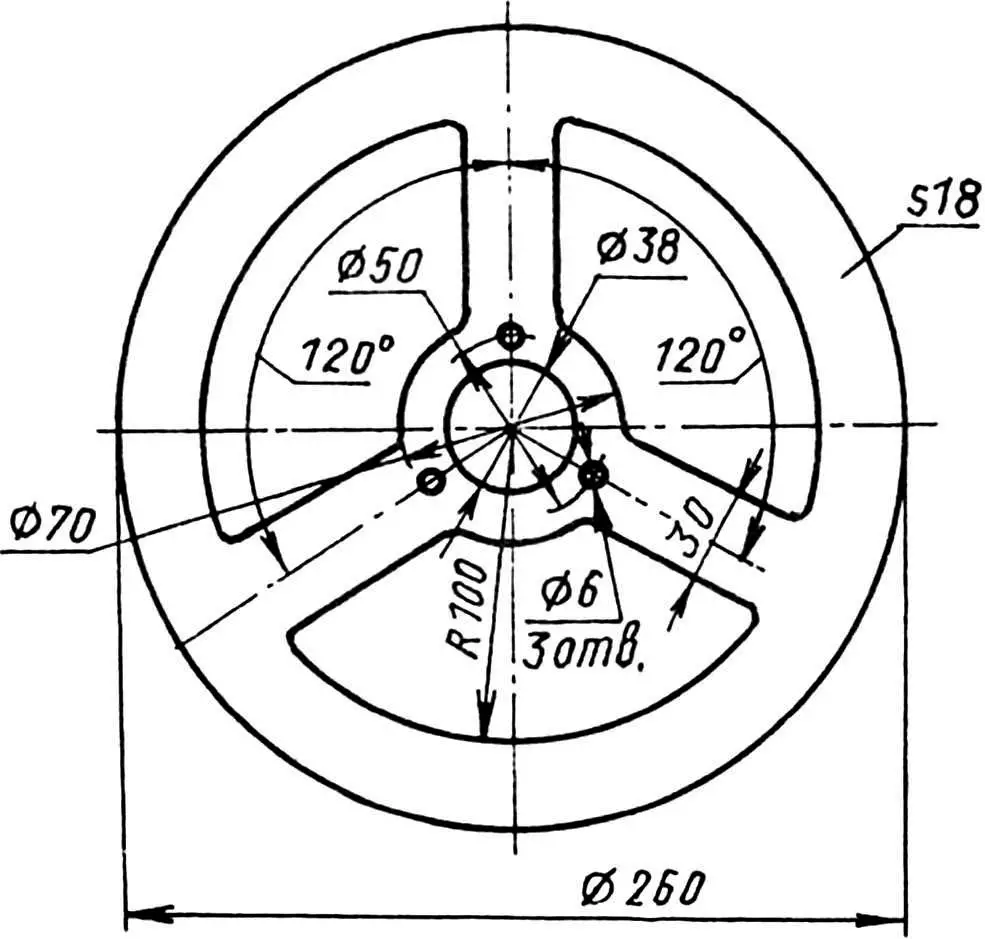
Torque from the electric motor to the rear left drive wheel is transmitted by a standard bicycle chain with a pitch of 12.7 mm through homemade sprockets. The drive sprocket, mounted on the shaft of the electric motor and welded to it, has six teeth, and the driven sprocket, welded to the standard one on the wheel, has 70 teeth. It is easy to determine the gear ratio: it is quite significant – more than 11.6.
The wings are made of a strip of hardboard and are connected with screws to arcs cut from 18 mm plywood. The rear wings are fixed to the front pillars of the subframe. The front ones are mounted on special brackets that are inserted into the pillars of the steering knuckles, and the wings turn together with the wheels. The sides of the fairing-hood are made of the same plywood. It is also covered from above with a sheet of hardboard. Between the sides (in their upper rear part) there is a dashboard.
All adjacent parts are fastened together with screws. The hood is pulled to the frame with five screws.
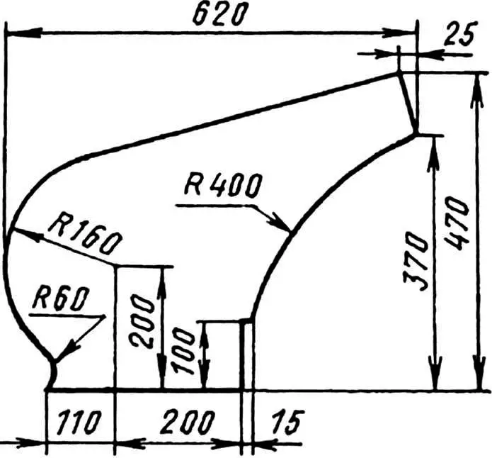
The seat can also be considered a facing element, since the electric car is a convertible type. The seat is comfortable and anatomical. It, like the fairing, consists of two 18-mm plywood sidewalls, but is covered not with hardboard, but with a sheet of 3-mm plywood.
Behind the seat back there is a battery compartment, closed by a door that rises upwards, also made of 18 mm plywood. All facing parts are covered with several layers of oil paint.
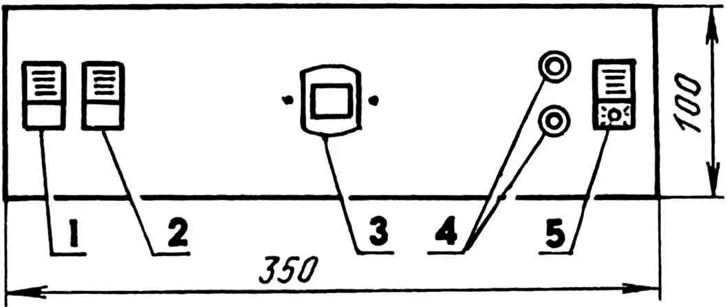
1 — side light switch; 2 — headlight switch; 3 — digital bicycle speedometer; 4 — headlight up/down buttons; 5 — voltage converter switch
An electric motor is secured under the seat on its front wall with two brackets and bolts. Since the wall is inclined, the chain tension can be adjusted by moving the motor.
The rear wheels of the electric vehicle are equipped with shoe brakes. The brakes are driven by a pedal, through a pipe to which the pedal is welded, and a cable.
The crew is equipped with a digital bicycle speedometer with a trip meter, front and rear parking lights with brake lights, an electronic horn, and a headlight.
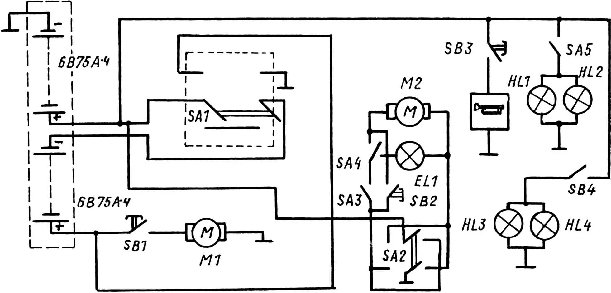
M1 — drive electric motor (modified starter from the Oka car); SB1 — drive electric motor on/off button (gas pedal); SA1 — drive electric motor and battery switching toggle switch; SA2 — headlight control toggle switch; M2 — headlight extension electric motor; EL1 — headlight bulb; SA4 — headlight up limit switch; SA3 — headlight down limit switch; SB2 — headlight on/off button; SB3 — horn button (on the steering wheel); SA5 — front parking light on/off switch; SB4 — brake light on/off button (from the brake pedal); HL1, HL2 — parking light bulbs; HL3, HL4 — brake light bulbs; power wires — from the batteries to the electric motor — 15 mm2 cross -section, the rest — 1 mm2
The brake lights are industrially made, and the front side lights are homemade, made from galvanized sheet metal.
The headlight is retractable (pop-up), has its own voltage converter. It is mounted in the middle of the hood-fairing. On the hood, a panoramic rear-view mirror is mounted on pillars-arcs.
Main technical characteristics of the crew:
Overall dimensions, mm:
length … 1570
width… 790
height (at the top of the wings) … 740
Maximum speed, km/h … 40
Operating speed, km/h … 20
Battery capacity, A*h … 150
Power reserve at 20 km/h, km … 25
Wheel size, mm:
front … 37-533
rear … 40-622
Track front/rear wheels, mm … 650/680
Wheelbase, mm … 830
A. POLIKARPOV, I. POLIKARPOV, St. Petersburg
Recommend to read
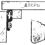 BARRIER TO DRAFTS
One of the ways of dealing with skvoznyaki in a modern apartment is to install a rubber door sealer, available in hardware stores. But here's the thing: if you provide a large preload,...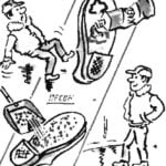 THE ICE IS NOT TERRIBLE
If the sole of the Shoe to spread waterproof glue, and then not very thickly sprinkled with sand, you will feel on the ice, as on earth. R. ASTRAKHAN
