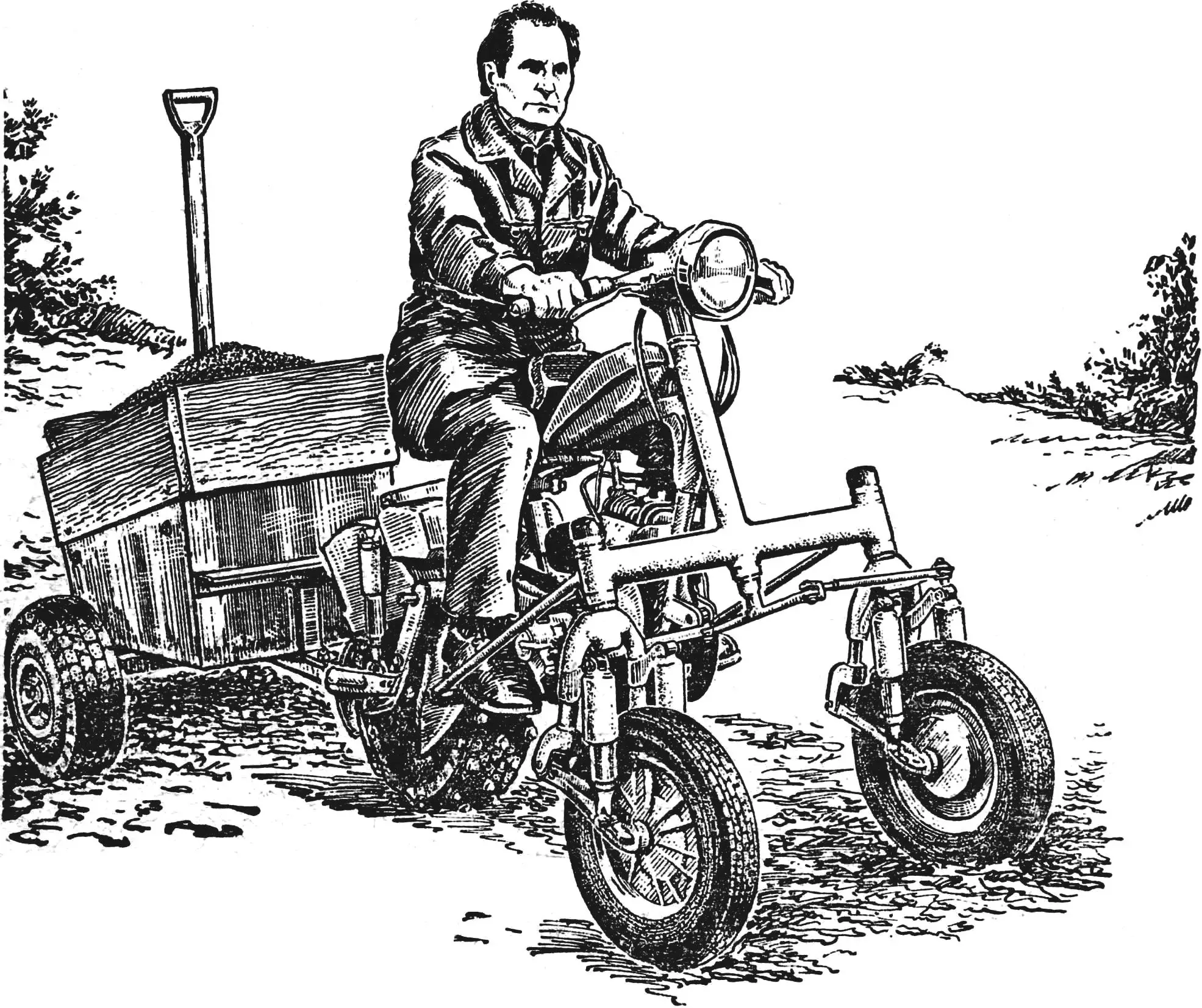
Original and practical designs by the Vinnytsia resident Oleg Andreyevich Ostapenko clearly appealed to the readers of our magazine. After a Central TV broadcast “This You Can”, in which the editorial office plays an active role, and a publication in “Fotopanorama” (see “M-K” No. 1 for 1986) of some developments by a self-taught designer, many requests about the features of these machines came to our letters department. That is why in No. 4 of the magazine for this year we published a description and drawings of the motoblock-tug, and now we present the pages of the issue for a story about a three-wheeled universal tractor-tug adapted for work in difficult terrain.
Perhaps the main thing that distinguishes all my machines is their ability to work in rough, uneven terrain. Both on the site and beyond it — along firebreaks and paths, away from well-trodden roads where, as you know, our equipment is not allowed. They often have to work on slopes with steepness of almost up to 25°.
That is why my three-wheeled tractor-tug, which will be discussed here, has the properties of an all-terrain vehicle. Its front steerable wheels come from a scooter, and the rear, driving wheel is a wide-profile pneumatic tire measuring 450×250 mm. Equipped with ground lugs — 48 steel conical spikes 40 mm high, arranged on the tire in four rows in a checkerboard pattern — it provides excellent traction even on waterlogged ground.
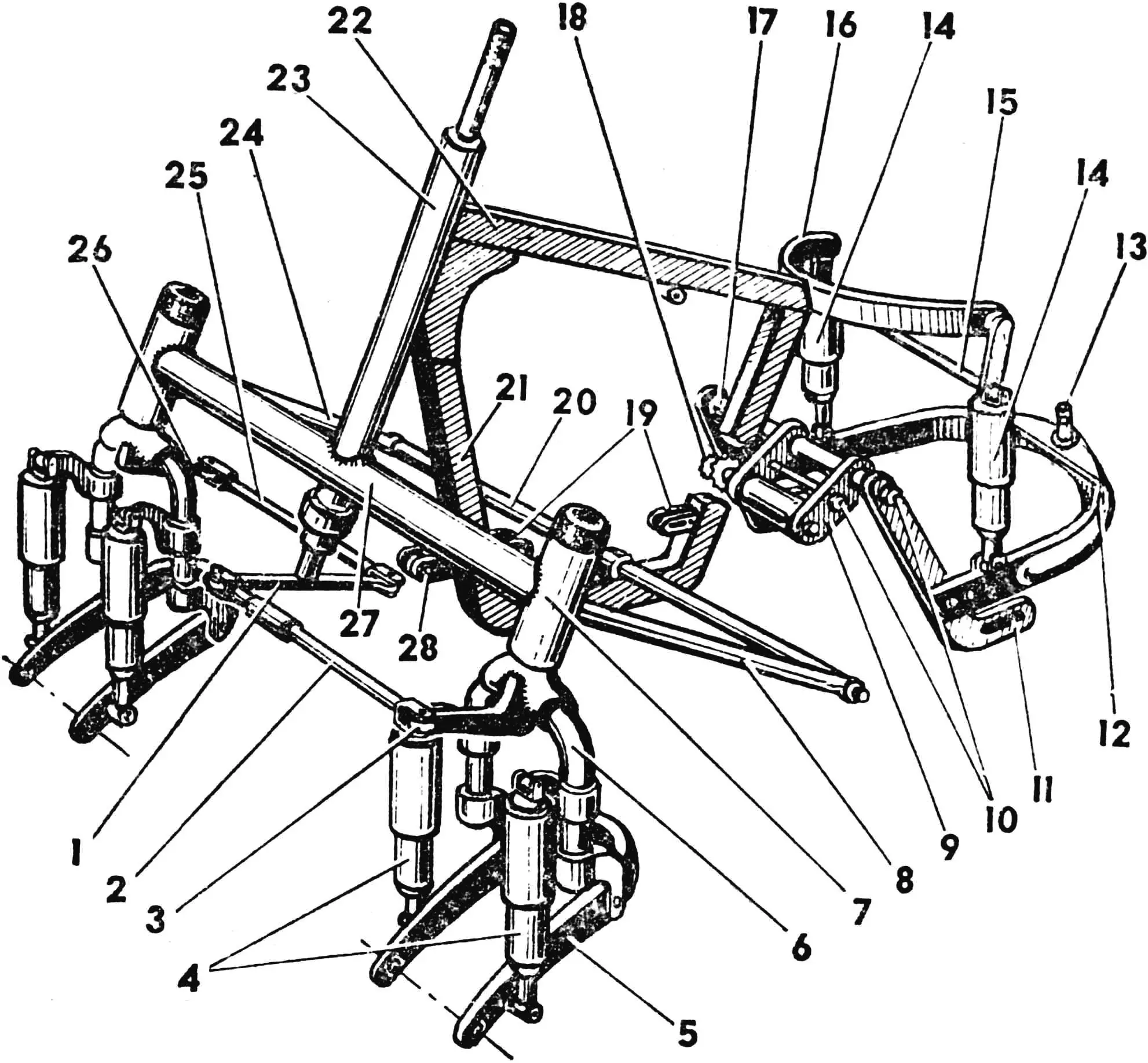
1 — steering lever, 2 — adjustable steering rod, 3, 26 — steering arms, 4, 14 — shock absorbers, 5 — wheel fork, 6 — suspension fork, 7 — suspension trunnion housing, 8, 24 — side rods, 9 — lugs, 10 — tie studs M12, 11, 17 — halves of the trailing-arm fork, 12 — towing bracket, 13 — towing pin, 15 — rear tie bar, 16 — shock absorber mounting bracket, 18 — sprocket block of the intermediate shaft, 19 — engine mounting brackets, 20 — footstep, 21 — lower beam, 22 — upper beam, 23 — steering column with steering shaft, 25 — non-adjustable steering rod, 27 — cross member, 28 — mounting bracket for the bulldozer blade.
The suspension of all wheels is independent, on six spring-hydraulic shock absorbers. Therefore the driver is not shaken at all over bumps. Moreover, his “cavalry” seat (the best that can be devised for such a machine; its shape, perfected over centuries, is very comfortable and holds the body well) also has an independent suspension with a similar shock absorber.
To increase lateral stability and improve traction with the ground, water is poured into the wheel chambers (up to 85% of their volume), followed by pumping with air up to 1 kgf/cm2 in the front and up to 3 kgf/cm2 in the rear. And yet, if steeper slopes than 25° come across the way, I prefer to get off and overcome the dangerous sections next to the tractor-tug moving in first gear.
In addition to towing at speeds up to 30 km/h with a trailer loaded up to 600 kgf, the tractor performs a number of other tasks. For example, it works with a front blade of a bulldozer type, an angled snowplow, mechanical forks for picking up and moving hay bales, a mower with a 1200 mm swath, a three-row hiller-cultivator, and a plow.
Traction power is provided by a T-200 engine with forced air cooling. The torque from the engine’s output sprocket (12 teeth) is transmitted by chain to an intermediate shaft (30 and 13 teeth), and from it to the rear wheel sprocket (46 teeth) mounted on the motor-scooter’s brake drum.
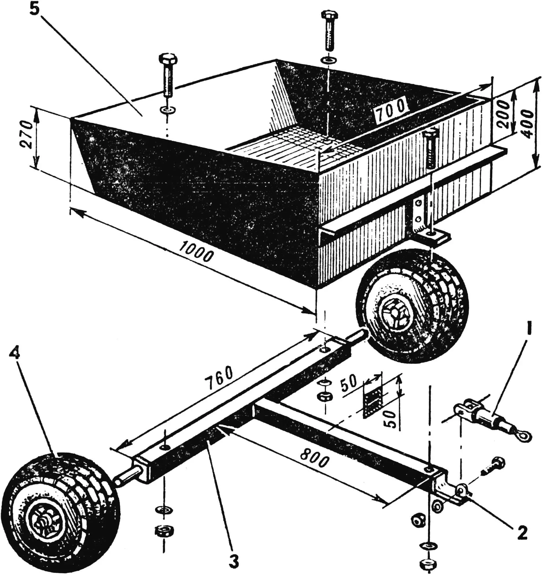
1 — drawbar, 2 — drawbar bracket, 3 — trailer frame, 4 — wheel, 5 — body.
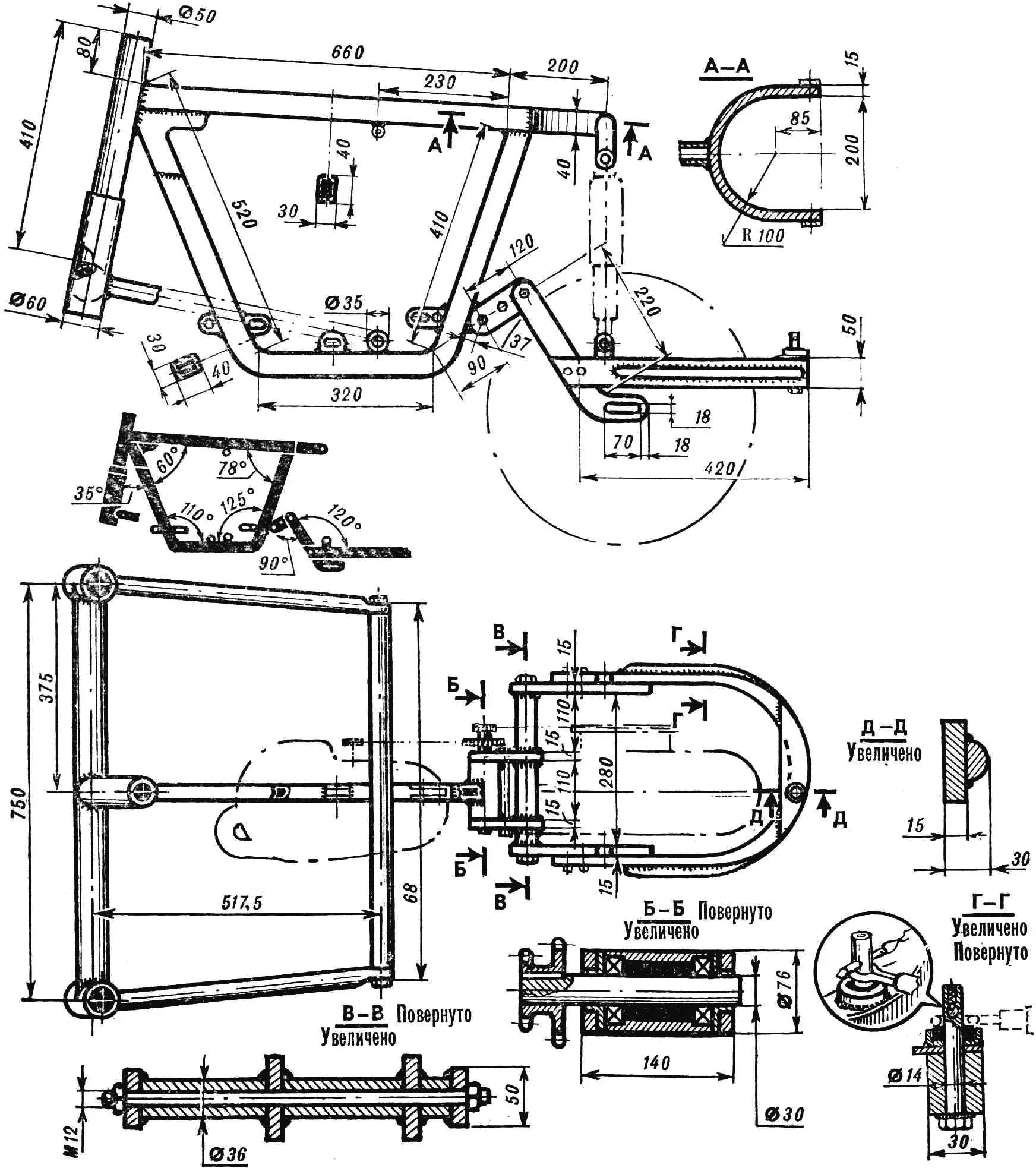
The frame of the tractor-tug is made from rectangular-section tubes and metal strips; ready-made units and parts are widely used. At first glance, its design seems complicated. However, this is not so. The front suspensions are taken from the “Elektron” scooter. The only modification is that steering arms 140 mm long are welded to them: on the right suspension fork — backward along the tractor’s direction of travel, and on the left — forward. The arms are connected by rods to a rocker attached to the steering shaft. The latter rotates in a column in thrust ball bearings. The steering wheel with the control arms and the lighting and control instruments is taken entirely from the scooter.
The engine is mounted on the lower frame beam on three brackets with elongated holes, which allow the engine to be moved slightly and thereby change the tension of the drive chain. Power is supplied from a moped fuel tank placed “like on a motorcycle” on the upper frame beam.
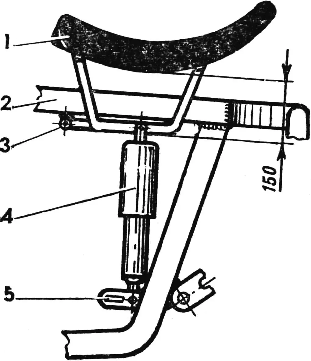
1 — seat, 2 — upper frame beam, 3 — tube bracket, 4 — shock absorber, 5 — bracket for mounting the shock absorber and engine.
The intermediate shaft cup is welded to the outside of the rear strut of the lower beam. The shaft rotates in bearings No. 206; it carries a block of sprockets (on a key) and lugs (on bronze bushings) of the trailing-arm fork. The latter are clamped together with an M12 stud. On the second M12 stud, the remaining part of the trailing-arm fork is assembled, welded from spacer bushings and two sections of a 50×15 mm steel strip, to which the towing bracket is bolted. The welding points must be very reliable, since they experience high loads.
The axle of the rear wheel is fixed in the lugs of the trailing-arm fork, which makes it possible to adjust the tension of the driven chain. It remains unchanged during vertical wheel oscillations, because the fork pivot axes and the intermediate shaft axes coincide.
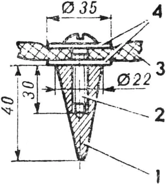
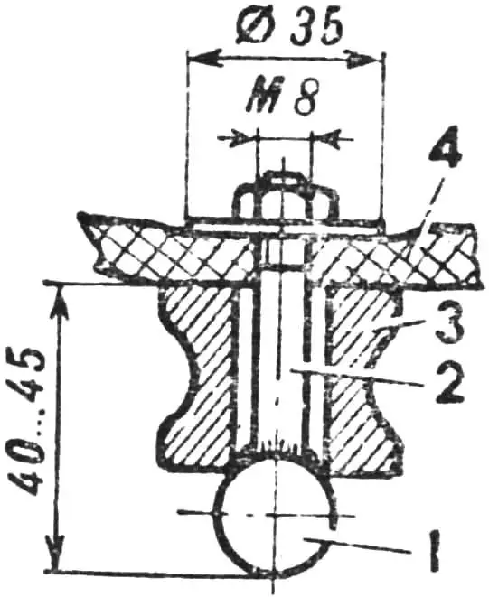
1 — spike, 2 — screw M10, 3 — tire, 4 — washers.
The towing bracket is a steel strip arc reinforced at the sides with two welded plates. At the rear, in its thickened part, a steel pin Ø14 mm is pressed in. Drawbars of the interchangeable working attachments, including the cargo trailer, hook onto it.
The trailer consists of a T-shaped frame welded from 50×50 mm steel profiles, whose ends are fitted with a drawbar bracket and trunnions; two pneumatics (they can be replaced with paired motorcycle wheels) and a body made of sheet metal. The body is installed on the frame so that the center of gravity of the load is located in front of the wheels. This slightly overloads the rear wheel of the tractor-tug, improving its traction with the ground.
1 — ball Ø 20 mm, 2 — bolt M8, 3 — ball bearing ring, 4 — tire.
It remains to add that the conical spikes with which the rear wheel of the tractor-tug is equipped are good primarily for soft ground. When driving over rocky terrain, it is better to use spikes made from defective ball bearings: they have good hardened steel, and the spikes will serve reliably and for a long time.
“M-K” 8’86, O. OSTAPENKO, Vinnytsia
Recommend to read
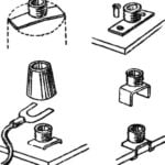 THE ELECTRICAL TERMINAL IS A FORMER TUBE
In Amateur practice it sometimes becomes necessary to connect to the layout of the electronic device or the measuring device of the connecting wires. Most convenient to do this using... PLAY?
PLAY?
A modern casino with excellent gambling attracts many, but to go there dare not everyone. Another thing — home electronic arcade. Here and nice and safe and the costs are minimal. On how...
