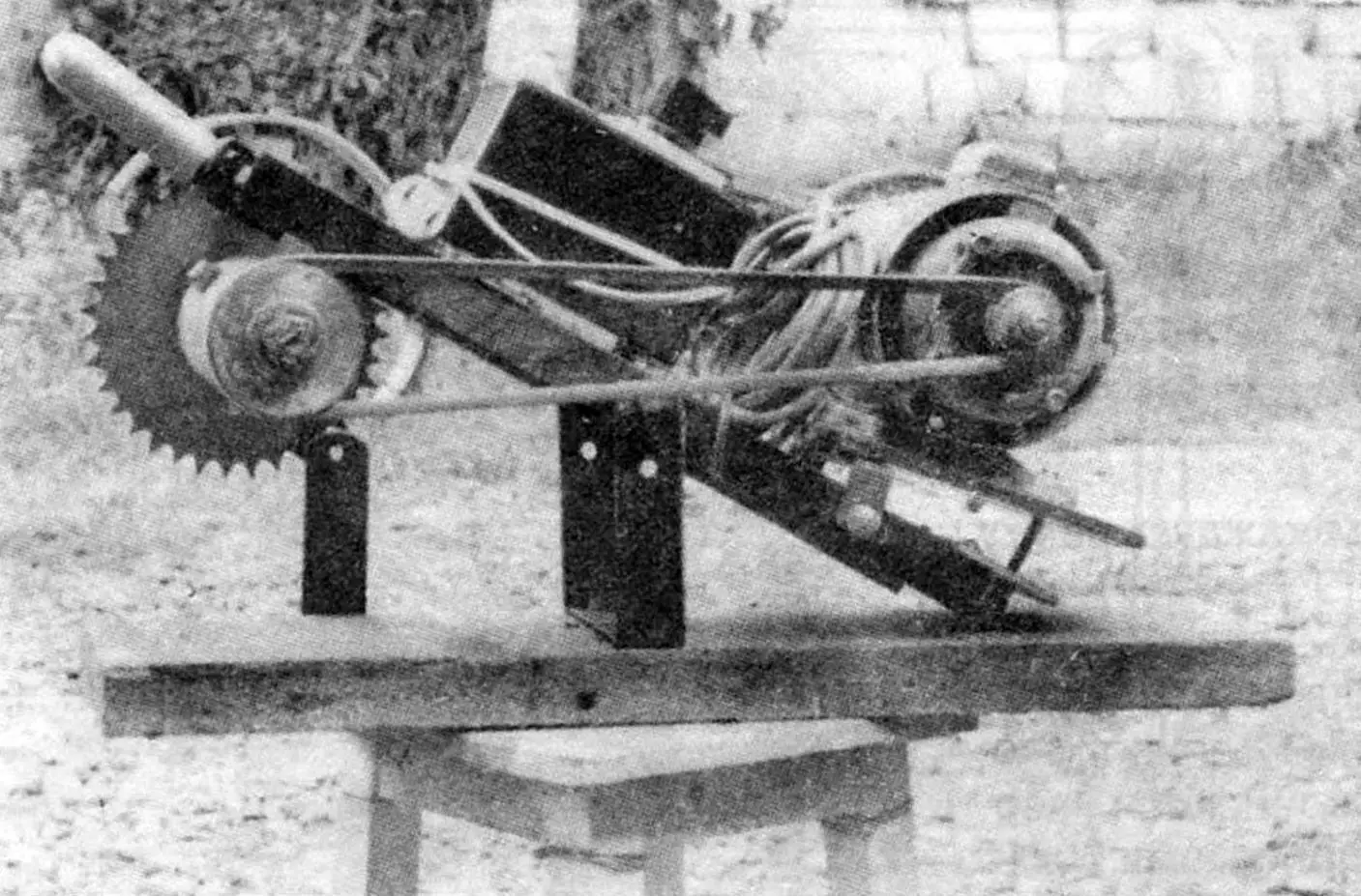
After pruning trees in the garden, a considerable amount of branches of various thicknesses ends up as waste. They are usually used as stove fuel. Thin branches are easy to chop with an axe, while thicker ones are sawn. Manual sawing is quite labor-intensive. To make my gardening chores easier, I built a portable circular electric saw. It is fairly light and compact. In addition, it is a balancing type, but more on that below.
The saw consists of a frame, with a drive shaft fitted with a 250 mm saw blade at one end and a 250 W electric motor at the other. Torque from the motor is transmitted to the shaft by an A-type V-belt. In the middle of the frame there is a housing with the starting equipment.
The frame with all mounted units swings on a balancing support, which in turn is fixed to a massive wooden base. This layout is advantageous because the mass of the electric motor balances the mass of the drive shaft relative to the balancing shaft, so working with such a saw is not tiring at all.
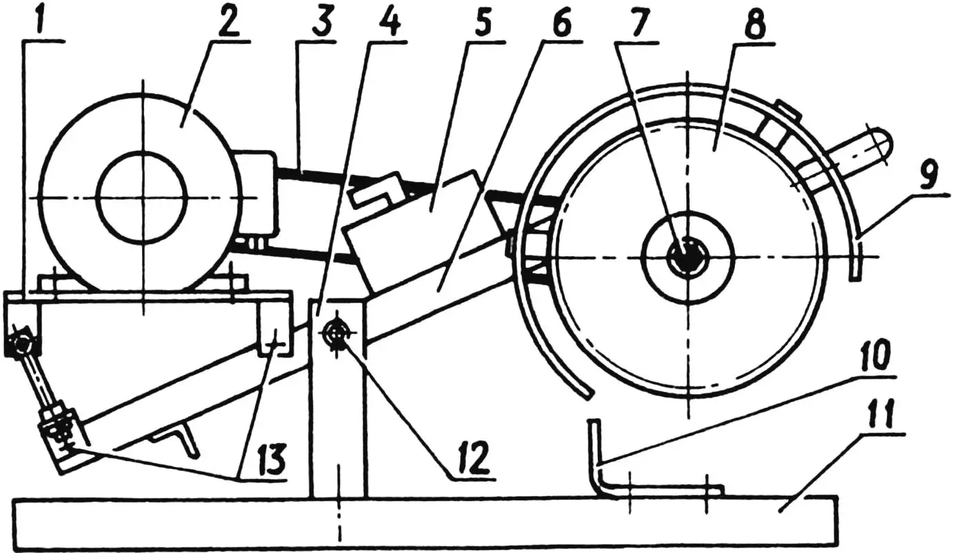
1 – electric motor mounting platform; 2 – electric motor; 3 – drive V-belt (type A); 4 – support (2 pcs.); 5 – starting equipment; 6 – frame; 7 – drive shaft; 8 – saw blade; 9 – guard; 10 – stop (2 pcs.); 11 – base (board); 12 – balancing shaft; 13 – M8 bolts for platform fastening (4 pcs.)
The saw “handles” branches up to 80 mm thick. Without intensive feed, the blade cuts to two-thirds of this thickness. To saw through the remaining third, the branch must be turned over. The relatively low power of the electric motor does not allow cutting through the full thickness of a thick branch in one pass. During sawing, the branches are held against shifting by a stop bent from a steel strip and fastened to the base with large screws.
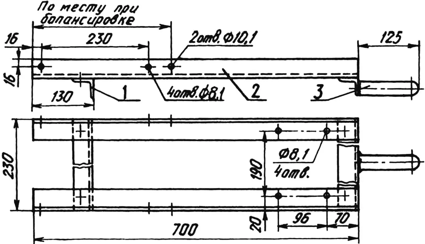
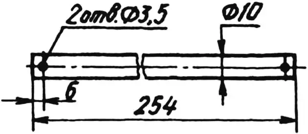
1 – crossmember (steel angle 36x36x4, 2 pcs.); 2 – rail (steel angle 36x36x4, 2 pcs.); 3 – blade feed handle
The frame design is quite simple: it is assembled from only four pieces of steel angle; at the front, a piece of 1-inch water pipe is welded to it, on which a handle made of insulating material is fitted – the blade feed handle.
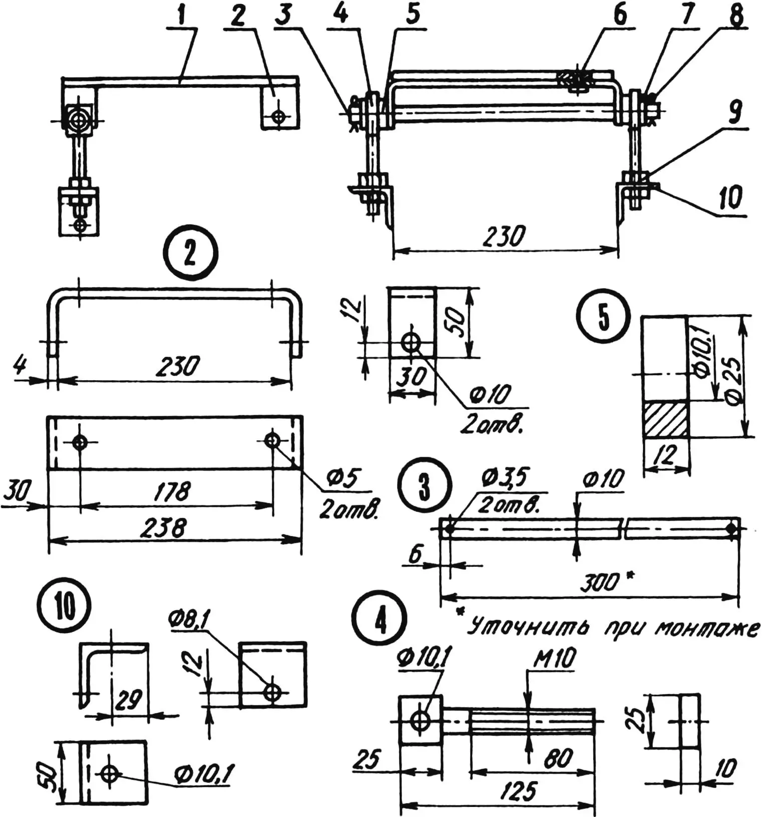
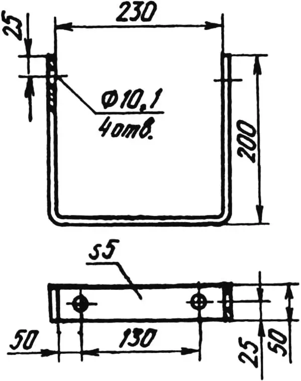
1 – plate (St3, sheet s3, 270×230); 2 – bracket (steel strip 30×4, 2 pcs.); 3 – pin (St3, rod Ø10); 4 – tension bolt (St3, 2 pcs.); 5 – bushing (St3, 2 pcs.); 6 – rivet Ø5 (steel, 4 pcs.); 7 – washer 10x25x1.5 (2 pcs.); 8 – cotter pin Ø3 (2 pcs.); 9 – nut M10 (4 pcs.); 10 – tension-bolt stop (steel angle 50x50x4, 2 pcs.)
The most complex unit of my saw is the drive shaft. It consists of a machined stepped axle rotating in two radial spherical double-row ball bearings 1205. The bearings are enclosed in ring housings, which are closed on both sides with covers and clamped to the frame angles with four M8 bolts. The saw blade is held on the axle by two friction flanges, and the pulley by a parallel key.
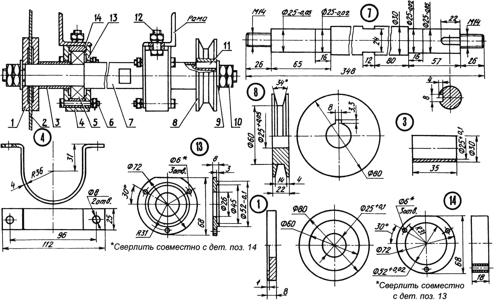
1 – flange (St3, 2 pcs.); 2 – saw blade; 3 – spacer bushing (St3, 2 pcs.); 4 – clamp (steel, 2 pcs.); 5 – bearing 1205 (2 pcs.); 6 – bolt M6 (6 pcs.); 7 – stepped axle (St3); 8 – pulley (St3); 9 – washer 14x32x3 (2 pcs.); 10 – nut M14 (4 pcs.); 11 – key 8x7x22; 12 – bolt M8 (4 pcs.); 13 – bearing cover (St3, 4 pcs.); 14 – bearing housing (St3, 2 pcs.)
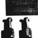
The electric motor mounting platform has a simpler design. The platform itself is a steel rectangle to which two U-shaped brackets are riveted. The front bracket is attached directly to the frame rails with M8 bolts, while the rear one is equipped with two tension bolts mounted on a common axle – a cotter-pinned roller made of steel rod. The threaded ends of these bolts go into angle stops screwed to the frame, which makes it possible to change the position of the platform (and with it the electric motor) relative to the frame and thus adjust the tension of the drive belt.
All other parts of the saw design are quite simple, for example the branch stop, so its drawing is not provided.
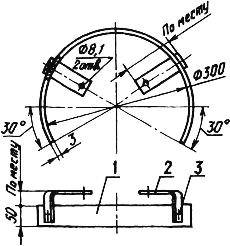
1 – protective rim (steel strip 50×3, L700); 2 – frame mounting bracket (steel strip 25×4, 2 pcs.); 3 – rivet Ø5 (steel, 2 pcs.)
Assembling the saw also presented no difficulties. The only installation challenge was mounting the frame on the balancing axle so that the electric motor side slightly outweighed the other side, and the saw blade in the non-working state remained raised above the base. This was achieved by selecting the frame position on the balancing axle using a series of holes pre-drilled in the vertical walls of the rails (they are not shown in the drawings).
It is certainly worth reminding that working with such a saw requires strict compliance with all electrical safety rules.
“Modelist-Konstruktor” No. 3’2003, A. MANGUSH
Recommend to read
 THE KNURLING MAKES THE FILE…
In the manufacture of models or devices containing frequently unscrews detail, there is often a need to do the knurling (knurled) outer surfaces of the nuts or screw heads. With this... HOW TO AVOID FLOOD
Many families today live in multi-storey buildings and use of household washing machines. Everyone who connects this machine (for electrical switchboards and sanitary communications),...
