A compact incubator in which you can hatch turkeys and chickens, ducks and geese, operates from an AC power supply.
The design automatically maintains the required temperature: chicken and turkey eggs are cooled twice a day, and waterfowl eggs — four times. In addition, the machine turns the eggs 180° every hour.
If something fails in the device — power is disconnected or a switch breaks, the water level drops or the clock stops, — an alarm signal is activated.
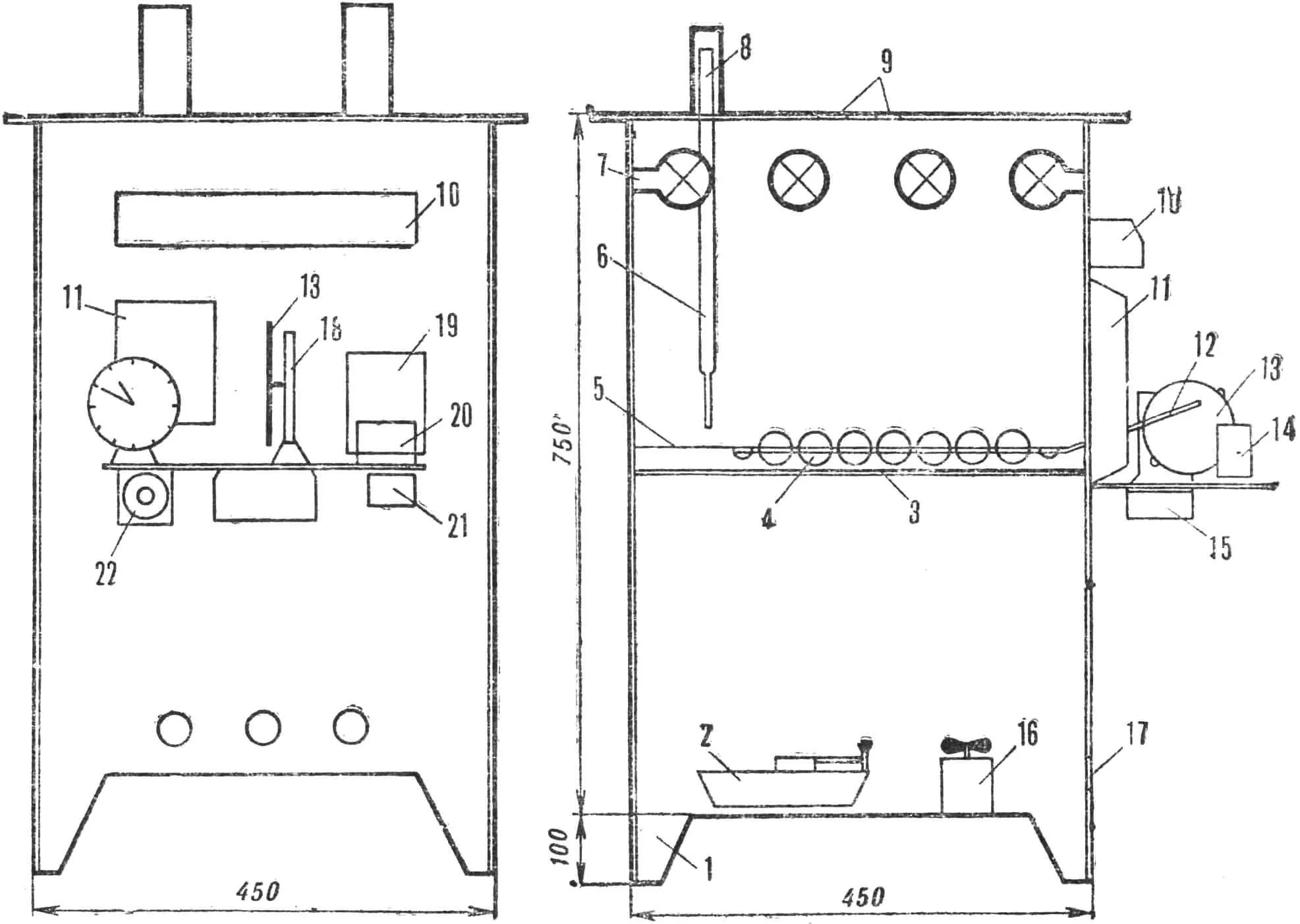
Fig. 1. General view of the incubator:
1 — housing; 2 — water pan; 3 — mesh; 4 — carriage; 5 — guide rods; 6 — sensor-thermometer; 7 — heating lamps; 8 — thermometer protective housing; 9 — ventilation holes; 10 — panel with toggle switch and signal lamps; 11 — relay unit; 12 — connecting rod; 13 — disk; 14 — clock; 15 — electric motor; 16 — fan; 17 — ventilation holes; 18 — reducer; 19 — transformer; 20 — rectifier; 21 — AC filter; 22 — automation activation button.
The automatic incubator (Fig. 1) is mounted in a cabinet 750 mm high, 450 mm deep and 450 mm wide. It stands on legs 100 mm high. A double-glazed observation window measuring 200×200 mm is made in the door.
In the upper lid in the middle there are three holes Ø 25 mm for thermometer-sensors, and on the right wall — three similar ones for ventilation.
On the outer side of the right wall of the cabinet, a shelf measuring 150×300 mm made of 4 mm thick textolite (it can be replaced with a metal plate) is attached horizontally. An alarm clock, transformer, rectifier, reducer, all relays enclosed in a telephone blocker housing, all toggle switches and a signal panel with bulbs are placed on the shelf. The arrangement of all parts on the panel is arbitrary. It is only important that the disk on the reducer axis is in the middle of the incubator chamber.
At the bottom of the panel, a motor and an AC filter are placed. The motor axis through a hole in the shelf should exactly exit against the reducer worm axis.
Inside the chamber, two sockets are attached to the rear wall and one on each side, so that the center of the bulb is 62—65 mm from the top of the chamber. At a distance of 330 mm from the top of the chamber, several thin wires Ø 0.6—1 mm form a support for a metal mesh with cells Ø 1.5—3 mm. Above the mesh is a carriage in the cells of which eggs will be placed. Two guide wires Ø 0.6—0.8 mm made of stainless material are stretched along its movement from wall to wall.
On the floor of the chamber stands a pan with a water level drop alarm contact fixed on it. Next to it — horizontally — a fan. The clock can be installed directly on the incubator panel, but they can also be placed on a table or in any other place by running four thin conductors to them.
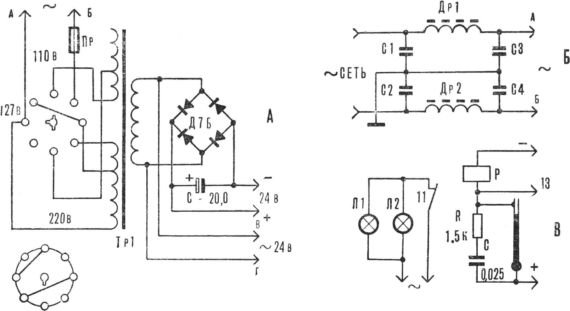
A — thermostat and rectifier; B — AC spark suppressor filter; C — thermostat.
A 24 V rectifier is made to power the relays and other devices. Its transformer is from any low-power radio receiver (Fig. 2). The iron is carefully disassembled, the coil is rewound. The upper filament and step-up windings on the coil are removed. The network, lower winding remains on the coil. A new winding is connected to a rectifier bridge consisting of four semiconductor diodes type D7A. An electrolytic capacitor (100 — 200 μF, 50 V) is connected at the output with “plus” to “plus” and “minus” to “minus” of the rectified voltage.
The AC spark suppressor filter was included in the circuit to eliminate sparking on the contacts. The filter chokes are wound on ferrite rods Ø 8 mm and 100—150 mm long and consist of 100 turns of PE wire, 0.6—0.8 mm each. Capacitors C1—C4 from 0.01 to 0.25 μF must be rated for operation at a voltage of at least 300 V.
DC spark suppressors consist of a series-connected resistance of 1—2 thousand ohms and a capacitor of 0.01—0.1 μF. The spark suppressor is connected in parallel to the contact where sparking is possible. To protect against AC sparking, one common filter is made, and to protect against DC sparking — a separate spark suppressor for each contact.
The thermostat (see Fig. 2) consists of a sensor-thermometer with a movable contact, heating lamps and relay RT.
The power and number of lamps depend on the size of the chamber, the thermal conductivity of the chamber walls, and the temperature of the room where the incubator is installed. Their operation is regulated automatically.
Minus 24 V is applied to one end of the relay winding. When the mercury of the sensor-thermometer rises to the set contact, the other end of the relay winding will receive “plus”, it will operate and turn off the heating. When the chamber begins to cool, the mercury will drop, break the contact and de-energize the relay — the heating lamps will turn on again.
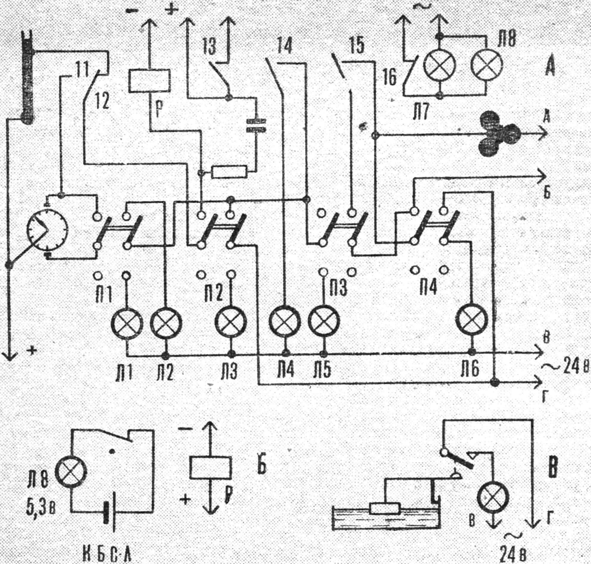
A — schematic diagram of the cooling regulator; B —- device for signaling temperature drop to dangerous limits; C — water level drop alarm.
Power to part of the heating lamps after the spark suppressor filter goes through the cooling relay contact ROX (Fig. 3). The other part of the lamps is powered through the thermostat relay contact. 24 V is applied to one end of the cooling relay winding. A second sensor-thermometer with a contact set at +30—32° is located in the incubator chamber. +24 V is applied to the mercury column of the thermometer.
The frequency of cooling and turning eggs is regulated by ordinary clocks, to the housing of which +24 V is applied. Contacts are installed on their dial (Fig. 4), insulated from the clock housing so that the hour hand, approaching the 12 and 6 divisions or any opposite ones, closes the contact. The dial is connected, in turn, to the relay P0 winding through relay contact 12, so through switch P the relay will operate, open contact 16 of the electric heating lamps, and through contact 13 supply current to relay RT, which will also turn off the heating lamps connected through RT. Contact 14 will turn on the signal bulb L4 “cooling activated”. Contact 15 turns on the fan, contact 16 — electric heating.
At the same time, contact 12 opens the circuit from the clock and the relay receives current from the thermometer through contact 11. As soon as the temperature drops below 30°, the contact in the thermometer will open, the relay will de-energize, the heaters will turn on, and the fan will turn off, and the chamber will begin to heat up.
The cooler is turned on only on the 12—13th day of incubation, and before that it does not work, which is signaled by bulb L3.
For contacts on clock dials, a short-cut (3—4 mm) telephone relay contact is used. These contact pieces are glued to the clock dial with BF-2 glue (through an insulating gasket if the dial is metal). A thin insulated conductor soldered to the contact is passed through a hole drilled in the dial. A piece of foil is soldered to the clock hand, which, touching the contact, supplies “plus” to the relay.
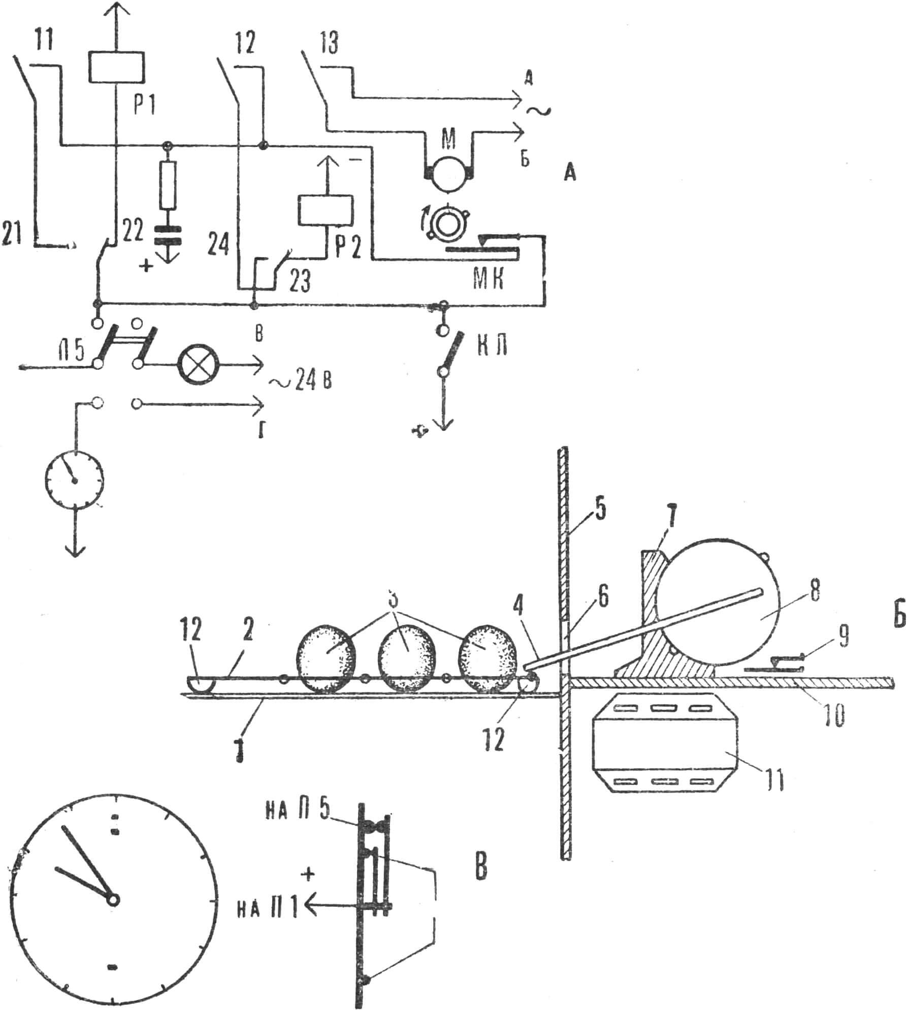
A — turner circuit; B — turner mechanism; C — clock contacts; 1 — mesh; 2 — carriage; 3 — eggs in cells; 4 — connecting rod; 5 — chamber wall; 6 — hole for connecting rod insertion; 7 — reducer; 8 — reducer disk; 9 — relay contact; 10 — panel-shelf; 11 — electric motor; 12 — carriage runners.
An asynchronous motor from an electric record player with a power of 35 W is used for turning (see Fig. 4). The movement transmission to the carriage is carried out by a reducer from a “Volga” car windshield wiper. A metal disk Ø 95—100 mm and 1.5—2 mm thick is fixed on the reducer gear axis.
Several holes Ø 3—4 mm are drilled in the disk at a radius of 35 mm, into one of which the connecting rod axis is installed. Several holes are made because the switched-off motor still rotates for some time by inertia, continuing to move the carriage.
Through a hole in the chamber wall, the connecting rod enters inside and connects to the carriage, rolling the eggs. A distance of 70 mm between the extreme positions of the carriage ensures the eggs are turned exactly 180°.
The turner has a toggle switch P-5 that turns it off and simultaneously turns on the signal bulb “turner automation disabled”. This process can also be controlled manually by pressing button KN.
When the disk rotates, two protrusions located opposite each other on it break the contact installed under the disk (from a telephone switch). Thus, every half-turn of the disk, the contact opens.
The motor start is performed by the same clocks that turn on the cooling. On these clocks, in addition to two hour hand contacts (see the cooling circuit), a third contact is installed, which closes on the minute hand every turn, that is, every hour. When closed, the minute hand contact supplies “plus” to relay RP-1 (“minus” is constantly applied to the other end of all relay windings) through contact RP-2-22. Relay RP-1 operates, starts the motor with contact 13 and prepares the circuit for relay RP-2 operation with contacts P and 12. As soon as the contact on the motor axis (MK) closes, the protrusion on the disk will already pass the contact. This can happen immediately if the start of operation coincided with the position when the protrusion has already passed the contact: relay RP-2 will operate and switch the power to relay RP-1. As soon as the disk on the reducer axis passes half a turn, contact MK will open by any protrusion on the disk and relay RP-1 will de-energize.
Although the minute hand of the clock has not yet passed its contact, the motor will stop, having passed only half a turn and moved the turner carriage toward or away from the motor by 70 mm.
As soon as the clock hand leaves its contact, relay RP-2 will de-energize and the circuit will return to its original position.
The turner carriage (see Fig. 1) is a grid made of steel wire Ø 2—2.5 mm, connected at intersections with copper wire Ø 0.5 mm and then soldered. The mesh cells are made so that an egg fits in them. The wire ends along the width are bent down through a rod Ø 10—12 mm and form runners on which the carriage can move.
The overall dimensions of the grid and the incubator capacity are determined by the chamber size. This design is designed for 42 chicken eggs.
When the clock with a closed cooling contact stops, an audible alarm is activated (see Fig. 3).
A power outage is indicated by a relay with a 2—3 turn winding, a 3.5 V bulb and a BKS-P battery. The bulb is connected to the battery through a relay contact, which is directly connected to the circuit and is constantly energized when power is supplied. The contact in this case is open, and the bulb does not light. When there is no current, the contact will close and the bulb will light up.
To maintain the required humidity in the chamber, water is poured into the pan. A contact from a telephone switch “monitors” its level. A lever with a foam float at one end, when the water level drops, closes the contact with the other end, and the bulb lights up.
Signal bulbs (telephone, switchboard, 24 V) are better connected to a 24 V winding to avoid overloading the rectifier, that is, to power them not with direct, but with alternating current.
The temperature regime is set as follows: the assembled incubator with thermometers, a water bath and heating lamps is connected to the network. The contact on the thermostat-thermometer is set to the 37.8° division. Lamps with a total power of 100—150 W begin to heat the chamber. As soon as the temperature rises to 37.8°, the contact will close, the relay will operate and turn off those lamps that are connected through the thermostat relay. The lamps connected through the cooler relay continue to burn, but they should be selected so that in this case the chamber temperature begins to decrease. After 3—5 min. it should drop below 37.8°, the relay will de-energize, and all lamps will light up again.
By selecting the lamp power and their connection scheme through both relays, the thermal regime is established. For the specified chamber dimensions, it is sufficient to connect 50—75 W through the thermostat relay contact and the same amount — through the cooler relay contact.
For effective operation of the incubator, it is necessary to know and strictly observe its operating mode. Here is the mode for incubating chicken eggs.
From the 1st to the 13th day — 37.7—37.8°. Humidity 54—55%, that is, 29.5—30° on the wet thermometer of the psychrometer. Turn every hour, do not turn on the cooler.
From the 13th to the 20th day — 37.4—37.5°. Humidity 47—48%, that is, 28—28.5 on the wet thermometer. Cool eggs 2 times a day to 30—32° C. Cooling should be done in 10—15 min. It is very important that after cooling, the temperature in the incubator is restored within 15—20 min. During cooling, the fan operates. Turning — one turn per hour. You can turn on the fan several times a day for 30—50 min. manually. From the 20th day until hatching — 37° C. Gradually increase humidity, at mass pipping bring to 70%, that is, 32° on the wet thermometer. Turn off the turner. Continue cooling 2 times a day. Do not turn off the fan. Transfer hatched chicks to brooders.
For other birds, the modes change somewhat.
O. BERLINER
Recommend to read
 Great Wall to a new level
The debut of the crossover class K2 of Great Wall Haval H8 was held in the spring of 2013 during the traditional auto show in Shanghai. Serial production began six months at the... WALL HOUSEKEEPER
There are options pocket of the housekeeper, similar to the wallet — but it for keys that you have to carry. But in the apartment a lot of different locks, locking all the cabinets,...
