 Among the variety of non-contact sensors are the most attractive for developers of motor vehicles, including improvised, turned out to be induction (or generator) — unpretentiousness to external conditions, ease of manufacture and durability. On the basis of “indukcionnye” was created by different devices: from the simple, registered linear motion, to complex, such as the ignition system with digital control, the fuel injection system, anti-lock braking system, brake control, etc.
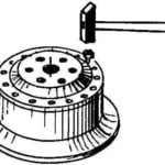
In the simplest case, the stator of the induction sensor consists of a coil with a coil core made of magnetic iron (steel) and a magnet. But the rotor is a gear drive or a rack with a number of teeth determined by the conditions of use of the sensor (Fig. 1A).
When the rotor rotates in the stator winding induced EMF occurs. When one of the teeth of the rotor approaches the winding, the voltage of IP increases to the maximum. Then, when the distance of the tooth, it changes the sign (Fig. 16). And characterized by a large slope of this voltage change that can be used to control electronic systems.
The voltage generated by the sensor depends on the speed of rotation of the rotor, the number of turns of the coil and magnetic flux generated by the permanent magnet. Because of the last two factors induced the IP reaches a maximum at maximum speed. If necessary (especially when the pulse repetition frequency is small) is necessary to strengthen the IP with the appropriate electronics (Fig. 1B).

Fig. 1. Typical design of an induction sensor (a) issued by the nm signal Uc (b), and a simple electronic circuit (C), amplifying and shaping it for future use in analog or digital form:
1 — platform with anisotropic magnet (reed keyboards); 2 — cheek; 3 — winding of the coil on Teflon strip); 4 — rod of magnetic material; 5 — rotor
Although very rare, but it happens that even “induktsionnyi” does not stand the test of Russian roads, a harsh climate and the almost complete absence of service in remote rural areas. Therefore, can be useful (especially for those who love to resolve his own problems) and more detailed information on the design of sensors. In particular, it is useful to know that the core in many inductive sensors are made of steel grades St1 — St3 and with a diameter of 3-8 mm must have a length of 25-30 mm. On it are pressed onto the a distance of 10-15 mm from each other of the cheeks of the coil (Fig. 1A), the external diameter of which is usually from 12 to 20 mm. PTFE gasket is wound winding coils, in bulk, to fill the space between the cheeks. Wire PEV-1, diameter of 0.06—0.1 mm. the Number of turns that fit in this case from 2500 to 4000.
On one side of the core, as a rule, provides space for attachment of anisotropic magnet. As the last repairmen, for example, using the magnet from the reed switch keyboards. The free end of the core is removed from the casing, which is made of nonmagnetic material. If required by the application, the transducer is filled with compound.
The rotor, if necessary, is made of magnetic material. The number of teeth is determined by the operating conditions. The gap between the stator and the rotor should be as low as possible.
It is worth mentioning another feature of inductive sensors. The voltage in the stator winding may occur when working not only with the special rotor, but with the gear teeth, bolted on the rotating part, or even when approaching/removing (fluctuations) of the special rod of soft magnetic iron. Hence, additional applications “indukcionnye”.
Sensor swing or strike (Fig. 2A). On the spiral spring of fine wire fortified a small piece of magnetic iron. When you swing or jerk it interacts with the stator of the sensor, which generates a series of aperiodic pulses.
Rotometer (tachometer) (Fig. 2B). The stator of the sensor of frequency of rotation cranked shaft of the engine mounted on the flywheel housing or on the plug of the observation flap in the vicinity of the flywheel ring gear. The device provides the most accurate determination of the rotation frequency without any invasion of the electric circuit of the ignition system.
Speedometer (Fig. 2B). For measuring the vehicle speed toothed rotor fixed on the output shaft of the transmission or the gear box unit is the flexible shaft. The system allows to refuse from expensive or unreliable mechanical tachometer flexible shaft.
Odometer (Fig. 2G). Measuring the way the car is using a timing disc, mounted on non-driven wheel. These sensors have also found application in the automatic braking system (ABS AntiBlockSistem), preventing blocking of wheels of the vehicle and its drift from “Yuz”.

Fig. 2. Schemes of work in cars induction sensor swing or strike (a), rotometer/tachometer (b), speedometer (b) odometer (d) and the ignition system with digital control PULSE TECHNIQUES of Dr. Artiga (d):
1 — stator; 2 — rotor (in the sensor of the swing and impact— the rod made of magnetic iron, rotometer/tachometer— gear ring of the flywheel, in the odometer — gear drive on the non-driven wheel); 3— spring; 4 — stator reference sensor; 5 — additional tooth of the ring gear on the engine flywheel
Wiper. Toothed sector fixed on the gearbox. Readings allow you to smoothly adjust the speed of the brushes depending on weather conditions.
Ignition system. Generator sensor (Fig. 1A) is the basis of the ignition system of the firm Bosh. The ignition system with digital control PULSE TECHNIQUES of Dr. Artiga used ring gear of the engine flywheel with the additional tooth to produce a reference signal (Fig. 2D). This system allows to very accurately adjust the spark timing.
If you go back to the design of the induction sensor, it should be noted that if the rotational speed of the rotor is influenced by parameters of the medium, the question arises about the braking moment exerted by the permanent magnet field. In this case, measures are taken to increase the breakaway torque (make the impeller larger).
And again. If the conditions do not need to control a small rotation frequency, the core can be made from hard magnetic material without additional magnet due to residual magnetism to ensure that the signal had sufficient value.
I. SEMENOV, Dubna, Moscow region
Literature
1. Bun B. electronics on the car. — M.: Transport, 1979.
2. Digital and analog circuits. Reference. — M. Rice, 1989.
3. 750 practical electronic circuits. Collection, M. Rice, 1987.


