Electronic devices based on microprocessors and integrated circuits are less sensitive to the parameters of the supply voltage. To ensure the safe operation of these devices use voltage regulators with protection. In many power supplies is reduced to cut power to the circuit if a short circuit in it or a sudden increase in load current. Such, for example, the popular voltage stabilizers КР142ЕН5.
“Minus” of such stabilizers is that they too are inert in the protection mode: triggered (stop the power supply to the circuit) going through the 200 — 500 MS and strongly depends on the nature of current change in the load on an abrupt increase in the current simple knots stabilizers react, and they tend to be smooth. Inertia protection is enabled within 200 MS can cost the owner dearly. In the literature published protective circuitry, responsive to the change in load current 100 not faster (nanoseconds), this is a very good indicator. However, they contain many elements and complicated for novice radio Amateurs. The author developed a more simple protection, triggered even with a smooth change of load.
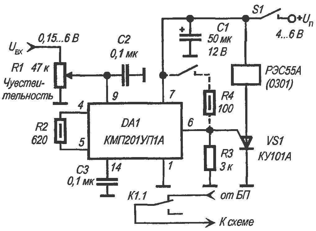
To repeat the proposed scheme can any Amateur radio operator. The node contains only one microspore КМП201УП1А does not require any configuration and adapts to any power source with a common negative wire. I recommend to embed the node in every home a power source for electronic works, and especially in those voltage sources that provide expensive components of electronic devices. Powered device DC stabilized voltage 4… 6 V, in “normal” standby mode consumes from the power source current of 0.8 mA. Through the normally closed contacts of the relay K1 is energized from the power supply unit (PSU) is supplied to the protected electronic circuit.

 Electronic devices based on microprocessors and integrated circuits are less sensitive to the parameters of the supply voltage. To ensure the safe operation of these devices use voltage regulators with protection. In many power supplies is reduced to cut power to the circuit if a short circuit in it or a sudden increase in load current. Such, for example, the popular voltage stabilizers КР142ЕН5.