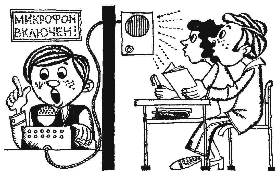
 In the staff room phone rang: asked physics teachers. Some of those present said: “Now it’s in the shop”. How to be? Because the school has no internal telephone communication and without the “intentional” here, perhaps, is not enough.
And it would be conveniently pressed the button on the remote intercom device and then transferred all that is needed in any academic study.
This form of communication can be used not only in school but in camp, in hospital, on the basis of tourism in many other places.
Camera intercom (Fig. 1) contains the microphone, amplifier, loudspeaker, call tone generator, rectifier and control panel. Power — AC voltage 220 V And connected the device to the network only during a communication session.
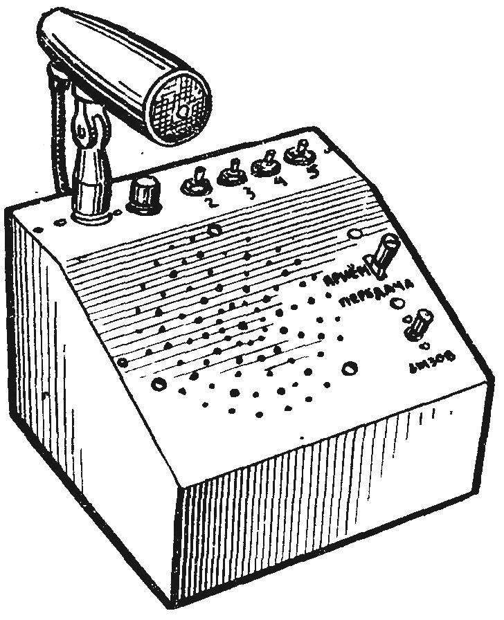
Fig. 1. Camera intercom.
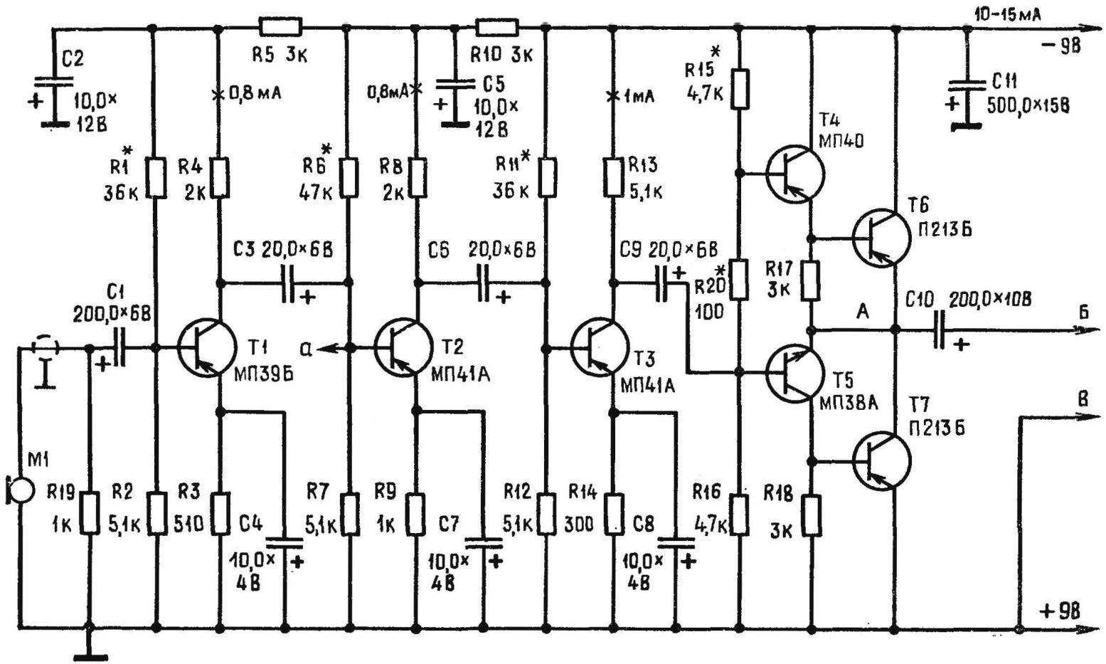
Fig. 2. Schematic diagram of the amplifier of an intercom.
Amplifier selector is made for transformerless circuit (Fig. 2). At the input of the amplifier are low impedance dynamic microphone MD-44, MD-45, MD-47, MD-64 and MD-200. In the first stage applied to the transistor МП39Б with low noise. The output stage is made with transistors T6, T7 in the push-pull scheme provides power to 1 watt.
Between pre-amplifier and power amplifier included panoinverse cascade transistors T4, T5 of different types of conductivity. Fazoinvertor provides two equal amplitude but opposite phase voltage required to initiate a push-pull stage. The lack of output transformer improves the frequency response of the amplifier: it is reproduced clearly and accurately.
Figure 3 presents the power amp circuit Board with the location details on it. The size of the Board 165X50 mm.
Generator touch tone calling is assembled on two transistors under the scheme asymmetrical multivibrator (Fig. 4). They generated the frequency of the fundamental tone is set by the resistance’ of the resistor R5 and the capacitance of the capacitor C1. In this case it is about 3 kHz. The generator is connected to the second amplifier stage (Fig. 2 and 4 marked “a”). The dial-tone generator is assembled on a printed circuit Board size 35X70 mm (Fig. 5).
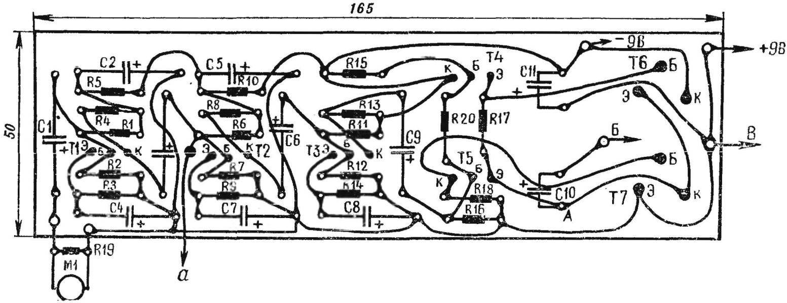
Fig. 3. The power amp circuit Board with the location details.
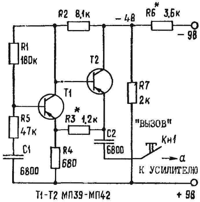
Fig. 4. Schematic diagram of the tone generator call.
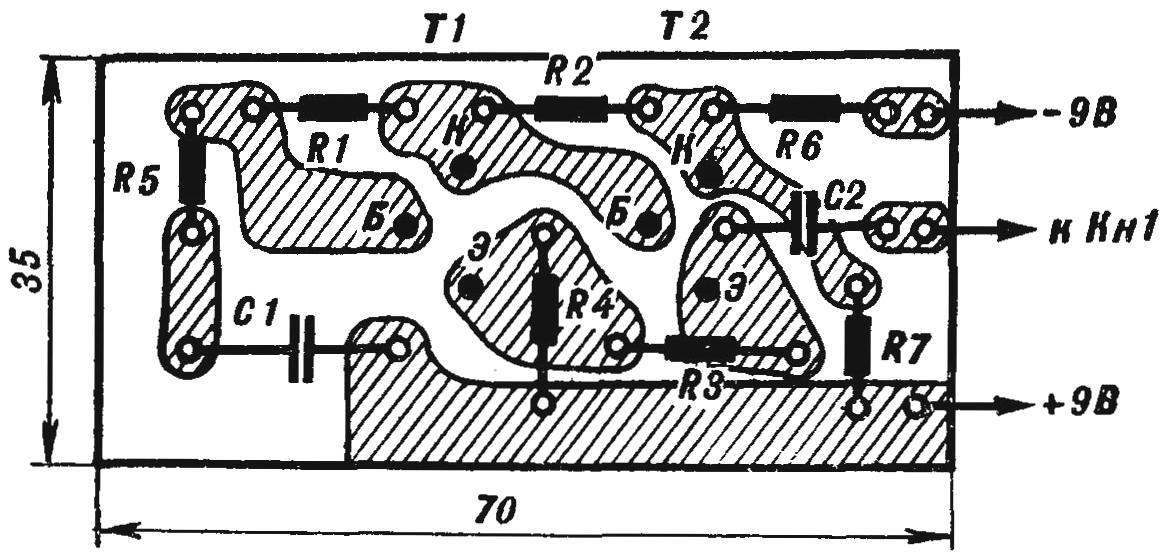
Fig. 5. Circuit Board tone generator call with location details.
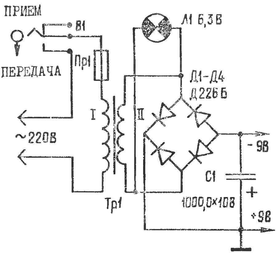
Fig. 6. Circuit rectifier communication device.
The amplifier and generator dial-tone are powered by full-wave rectifier (Fig. 6). A rectifier connected to the network via the phonebook key in the position “Transfer”.
Transformer TP1 is assembled on the core Ш12Х22 mm. Winding I contains 1200 turns of wire PEV-1 0,12 and the winding II — 40 turns of wire PEV-1 to 0.8. You can use a standard filament transformer, for example, from TV’s “Record” or the output transformer from the same radio. In the latter case, you should resolve the gap, collecting the plates so that they overlap each other.
All nodes in the communication device is fixed on the panel of insulating material 165X 165 mm (Fig. 7) and install into the housing. On the top cover of the device, made of sheet duralumin with a thickness of 1,5 — 2 mm attach the speaker 1ГД-5, the button tone call switch “Reception — transmission” is a combined telephone key KTRON 3-3/8-3,
the toggle switch TV2-1 call indicator light MN-14 (6.3 V X 0.18 A) and microphone Jack.
The housing side wall can be made from pieces of plywood with a length of 190 mm and thickness 6 — 8 mm. the height of the front and rear walls 75 mm and 125 mm, respectively. To the rear is attached a connecting module for connecting the communication lines.
The establishment of a scheme of the device is reduced to the measurements of the voltage on the capacitor C1 of the rectifier: it is 9 V. Next, check the modes of the transistors. The magnitude of the collector currents set by selection of resistance of resistors is indicated in the diagram with an asterisk. When adjusting the output stage of the amplifier, the resistor R20 is replaced by a variable resistance 150 — 200 Ohms. His slider is set to the minimum resistance. By choosing the values of resistor R15 sets the voltage at point A (Fig. 2) is equal to -4,5 V. 4 by using variable resistor make the amplifier consumed current of 10-15 mA. By measuring the resistance, variable resistor replaced by an equivalent constant.
The transistors T4, T5 should be selected in pairs in the amplification factor VST = 50 — 60 and the reverse current of the collector transition I to = 1 — 3 mA; T6 — T7 — V St = 30 — 40, I to =5-15 mA.
Generator the dial-tone test with the help of headphones, such as the TONE-2, connecting them to the output of the circuit. Generation in case of its absence set by selection of resistor R3. The generator used transistors with a gain of at least 80.
Fig. 7. The location of the circuit elements of the negotiating device.
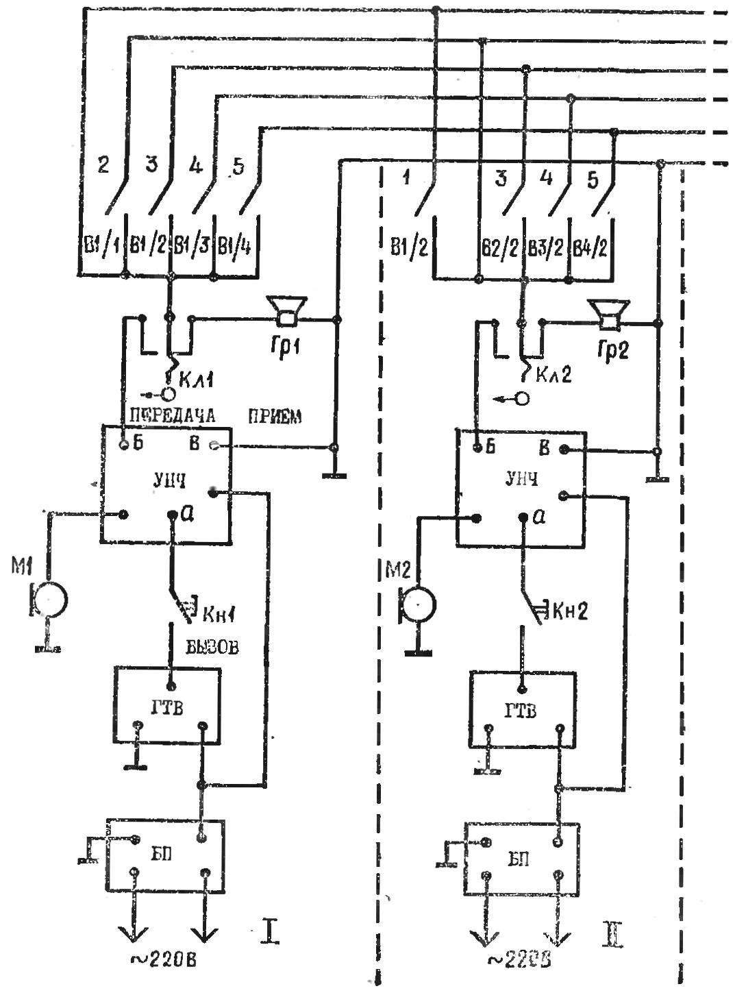
Fig. 8. Connection diagram of devices to the communication line.
Now about connecting devices to the communication line. Figure 8 shows a diagram of switching between five subscribers (if you wish, subscribers can be increased to 9-10). Every subscriber can contact any other or to send a message to all simultaneously. Let’s trace the process of determining when the first subscriber with the fifth. The first includes on your camera switch 5, closing the contact B1/4. Then puts the switch “Reception — transmission” to “Transmitting” and by pressing the button “Call”, sends the caller a dial tone. After hearing the call, the fifth subscriber includes in his apparatus a switch 1 and switch by turning the key “Reception-transfer” to “Transfer” corresponds to the first subscriber.
The device is a phone key from one stable position. Therefore, the possibility of failure due to forgetfulness of the subscriber excludes: switching to standby is received automatically. The indicator device is a lamp which lights up in the mode of “Transmission” and goes out in the mode of “Reception”.
B. TAILOR, H. PONOMAREV
Recommend to read
 Micromotorcycle “Gnome”
Maximum simplicity of design and minimal complexity of manufacturing - these are the principles that were used as the basis for the creation of the Gnome micromotorcycle (see... VEST PAINTER
Anyone who had to work with a spray, and even a room, knows how harmful "for the respiratory system. Meanwhile, the problem of protection is not too complicated. We only need to create...
