 A variety of machines are used to evaluate sports competitions. Automatic light displays have become commonplace at hockey games and at competitions of figure skaters and boxers, weightlifters, and gymnasts. It is usually complicated electronic device.
A simple cybernetic machine with a light Board can be made for competitions in schools, colleges, and institutions. She will put one of the two values: “Yes” or “no” (Fig. 1). To apply this the judge panel of three to five arbitrators, of whom one shall be Chairman.
Control cybernetic machine, use the voting buttons judges KN1—Кн5, buttons Кн6 “Reset” switch B1 “Number of judges”. If the judges vote in the affirmative, they click on one of the buttons KN1—Кн5: fires connected in series with it the solenoid. Switch B1 switches the machine to an operating mode with three, four or five judges.
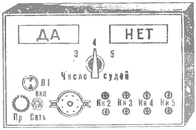
Fig. 1. Light Board “cybernetic arbitrator”.
Executive (logical) circuit of the machine are the relay contacts R1/2—R1/6, P2/2—P2/6, P3/2—P3/6, R4/2 and R4/6 R5/2 and R5/6, lights L2 and L3, the key B2 (Fig. 2). L2 illuminates the display “Yes”, L3 — display “no”. The Chairman closes the key B2, when it will expire the time allotted for voting: lights one of the bulbs — L2 or L3.
How’s that car running?
Assume that the panel of judges consists of three judges. The signal “Yes” the machine will give when two of them vote in the affirmative, in other cases, the scoreboard lights up, “no.” If none of the buttons KN1 — Кн3 not pressed (Fig. 2) then with the closure of the key B2, the light L3 is “no”: current passes through the contacts P2/3, RZ/6.
Let’s say that the second and third judges vote in the affirmative. They click on the button Кн2 Кн3 and relays P2 and P3 are activated, and the closed contacts R2/1 and R3/1. Contacts P2/3, P2/4 and P3/2—RH/6 perform the necessary switching in the logic circuit. Now, if you close the key B2 lamp will light L2 Yes: it included contacts P2/3, P3/2.
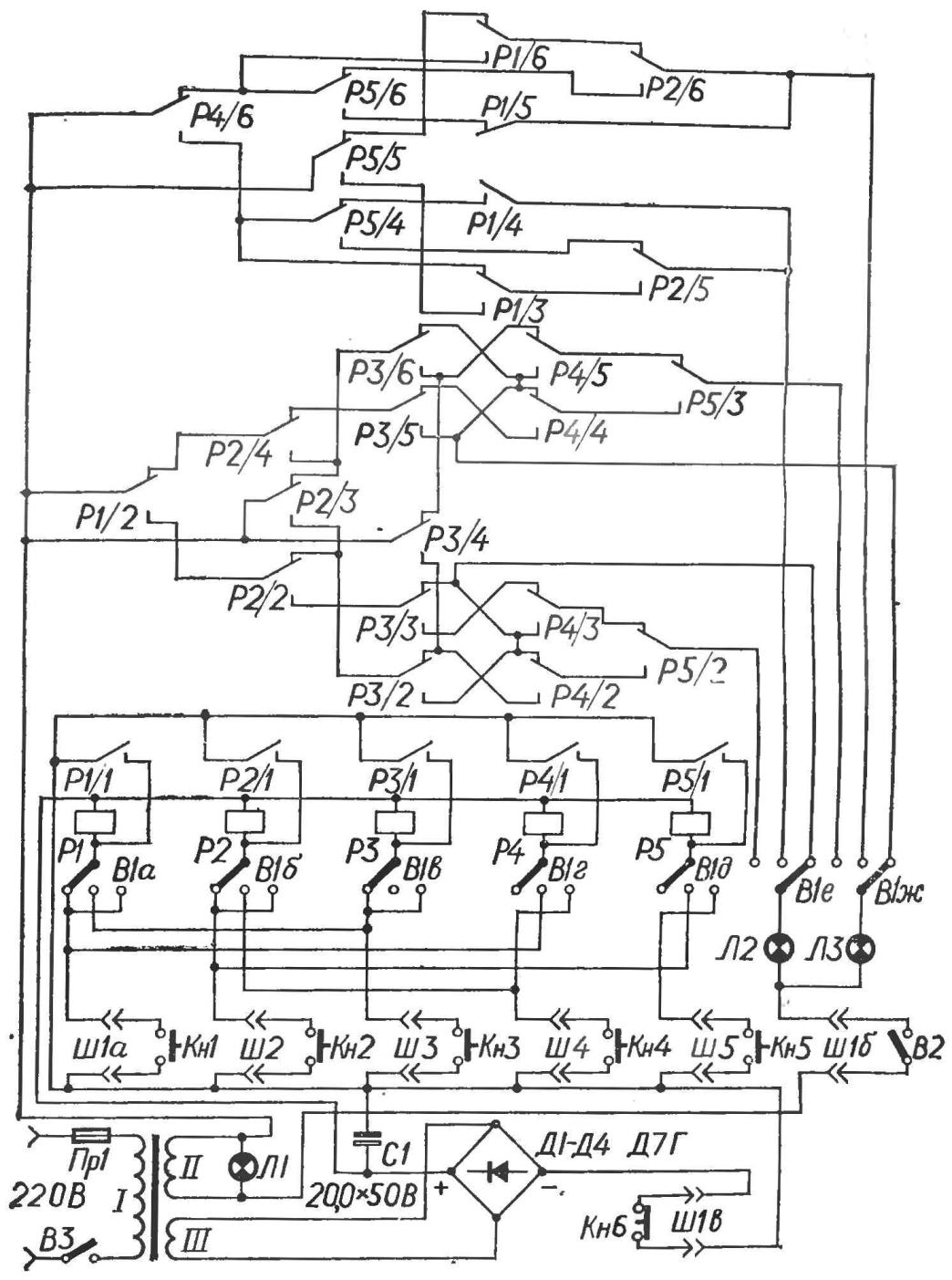
Fig. 2. The machine concept.
The machine can operate in a different mode when in the panel of judges included four judges. The signal “Yes” illuminates when the majority of the affirmative votes, and if two positive ratings and one will belong to the Chairman. In other cases the machine will answer “no”.
Switch B1 is a middle position. To the button of the Chairman of the KN1 connects relay R4, to the button Кн2 relay R5, to the button Кн3 relay R1 and to the button Кн4 — relay R2. Кн6 button is disabled. Relay R3 in the operation of the control circuit is not involved. In the Executive chain included contacts P4/6, P5/4—P5/6 P1/3— P1/6, P2/5 and P2/6, the bulb L2, L3, and the key B2.
Assume that you will vote down buttons Кн2 and Кн3. Trigger relays R5 and R1, contacts R5/1 and P1/1 are closed, providing a lock these relays. The contact R5/4—P5/6 and Pl/3—P1/6 produces switching in the scheme. With the closure of the B2 key will light the bulb L3: the circuit is now closed contacts R4/6, P1/6 P2/6.
Now let the buttons hit the President of the ground jury a fourth judge. Contacts R4/6, P2/6 and P2/5 in the Executive chain switch. When closed the key light W2 L 2 (signal “Yes”): the current passes through the contacts R4/6, PI/3, P2/5.
If the jury consists of five judges, the signal “Yes” the machine will be given at three, four and five affirmative votes of Board members.
The machine worked in a given mode, the switch B1 will be transplanted in the next or third position. The work involves all five relay control circuit. If affirmative votes are missing and the key B2 is closed, the light L3 (signal no).
Suppose that the vote is in the affirmative the first, fourth and fifth judges of the pressed button KN1, Кн4 and Кн5. Trigger relay PI, P4 and P5. With the closure of the B2 key lamp will light L2 (signal “Yes”): light bulb circuit closed by contacts Pl/2, P2/2, RH/2, R4/2 R5/2.
After each cycle of the machine leads to the initial state by pressing the reset button Кн6.
In “cybernetic jury” can be used neutral electromagnetic relays of any type, designed for a voltage of 24 V and having six contact groups. It is possible to use a relay with a smaller number of contact groups, for example, the relay RES22 or RES9. Then, instead of each of the relays R1—R5 in the circuit include two or three relays in parallel.
Switch B1 is recruited from the four 5П2Н biscuits or three biscuits 3П3Н. As the mains switch B3 and an answer key B2 used in single-pole or double-pole toggle switches.
Button Ки1—Кн5 — bell. Button Кн6 with normally closed contacts made of zvonkovoe in the following way. The petals of the contacts straighten and shorten so that the resulting gap between them was about 4 mm. To the head of the screw holding the button, solder a washer of appropriate dimensions. If the button is not pressed, the washer connects the lobes of contacts. Lamps L1—LZ is designed for 6.3 V, 0,28 A.
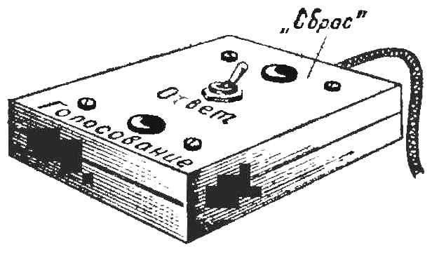
Fig. 3. Remote control.
As TP1 can be used by any power transformer, but it needs to be redone: to wind the winding on the 24 V to power the solenoid.
With the frame of the transformer and remove the coil to supply the anode circuits of tube radios. Instead, it is wound the other with a certain number of turns, which depends on the type of the transformer. For example, in the power transformer from the radio “Record” coil should have 150 turns of wire PEL of 0.4—0.5. Filament winding is retained and is used to supply the lamps L1—LZ.
Remote control of the Chairman of the panel of judges is assembled in the case from a pocket radio receiver (Fig. 3). It hosts buttons KN1 “Vote”, Кн6 “Reset” and the switch B2 the Answer. The remote connects to the car via a connector SH1, made of cap and sockets from octal tubes.
Tube socket and socket ø2— Ш5 through which connected voting buttons Кн2—Кн5, mounted on the front panel “cybernetic arbitrator” made from a PCB or Micarta thickness of 4-5 mm.
Correctly assembled machine s needs to be establish and always ready to work.
S. NOVIKOV, Sverdlovsk
Recommend to read
 Trailer tester
To check the operation of the trailer's lighting system, two people are needed: the driver turns on the switches and presses the brake pedal, while an assistant monitors whether the...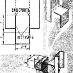 HAND, AND AS LARGE
Commercially available small vise with a clamp to hold or to tighten to the table — depending on the workpiece. However, along with this advantage there is a disadvantage: if we clamp...
