
Among self-defense devices, electroshock units (ESU) are far from the least notable, especially in terms of psychological impact on attackers. They are, however, quite costly, which motivates radio amateurs to build homemade analogues (see, for example, the detailed article on this in issue No. 5’99 of “Modelist-Konstruktor” magazine).
Without claiming to be highly original or groundbreaking, I offer my own design, which anyone who has ever wound a transformer and assembled the simplest circuits—such as a crystal receiver with a one- or two-transistor amplifier—can replicate.
The core of my device (Fig. 1a) is a transistor oscillator that converts DC from a power source such as a “Krona” (“Korund”, 6PLF22) battery or “Nika” rechargeable cell into stepped-up AC, together with a standard voltage multiplier U, whose design and operation are described in detail in issue No. 5 of “Modelist-Konstruktor” for 1997. A very important part of the ESU is a homemade transformer (Fig. 1b and Fig. 2). Its core is a ferrite rod 8 mm in diameter and 50 mm long. Such a rod can be broken off, for example, from a radio receiver’s ferrite antenna, after first scoring the original along the circumference with the edge of an abrasive stone. The transformer works more effectively, however, if the ferrite is from a TV line output transformer (LOPT). In that case, a cylindrical rod of the required dimensions must be turned from the base U-core.
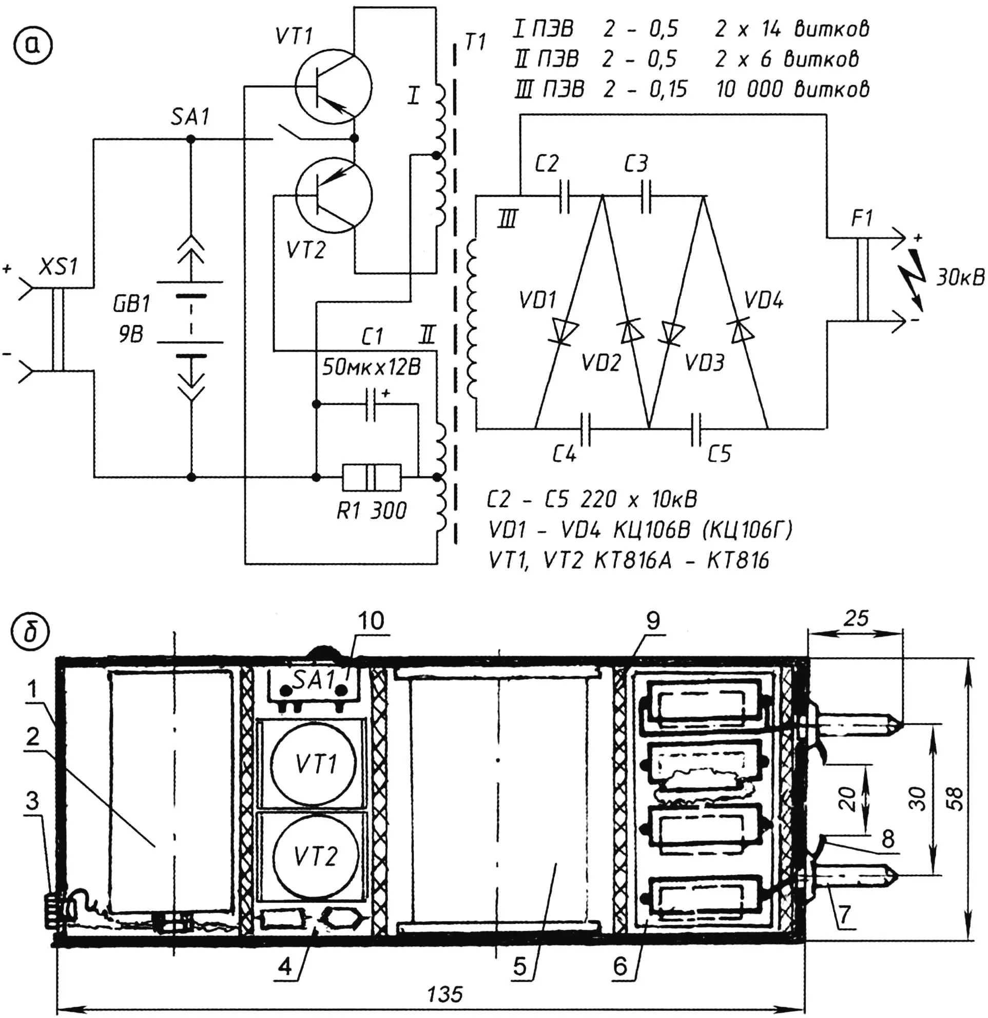
1 — case (plastic soap dish 135×58×36 mm, 1 mm wall); 2 — power source (“Korund”/“Krona” battery or “Nika” accumulator); 3 — coaxial micro socket; 4 — transistor voltage converter oscillator; 5 — homemade transformer; 6 — voltage multiplier; 7 — discharge electrodes (brass pins from Euro plug, 2 pcs.); 8 — safety “whiskers” (brass, 2 pcs.); 9 — protective partition (4 mm vinyl plastic or acrylic); 10 — slide switch; items 3 and 10 — from pocket radio
The coil former is a 50 mm length of plastic barrel from a used marker, whose inner diameter matches the ferrite rod. Cheeks 40×40 mm are cut from 3 mm vinyl plastic or acrylic sheet and firmly bonded to the barrel with dichloroethane at the seating surfaces.
For the windings, enameled copper wire with high-strength vinylflex-based insulation is used. Primary 1 has 2×14 turns of PEV-2 0.5 mm. Winding 2 has almost half as many—specifically 2×6 turns of the same wire. The high-voltage winding 3 has 10,000 turns of finer PEV-2 0.15 mm.
For interlayer insulation, instead of polytetrafluoroethylene (PTFE) or polyethylene terephthalate (Mylar) film usually recommended for such windings, 0.035 mm capacitor interlayer paper is quite acceptable. It is advisable to obtain it in advance: for example, from 4 µF LSE1-400 or LSM-400 capacitors from old fluorescent lamp ballasts that have long since reached the end of their service life, cut to the exact working width of the future transformer’s former.
After every three wire layers in the author’s version, the growing winding was brushed with epoxy adhesive slightly thinned with acetone (so that it was not too viscous), and two layers of capacitor paper insulation were laid. Then, without waiting for it to cure, winding continued.
To avoid wire breakage due to uneven rotation of the former during winding, the PEV-2 0.15 was passed through a ring. The ring hung on a spring made of 0.2–0.3 mm steel wire, gently tensioning the wire upward. Between the high-voltage and the other windings, six layers of the same capacitor paper with epoxy were used as breakdown protection.
The winding ends are soldered to pins passed through holes in the cheeks. Alternatively, leads can be made without breaking the wire by folding and twisting the same PEV-2 in 2, 4, or 8 strands (depending on wire diameter).
The finished transformer is wrapped in one layer of glass cloth and potted in epoxy. When assembling, the winding leads are pressed against the cheeks and routed with maximum separation from each other (especially for the high-voltage winding) into the appropriate compartment of the case. This prevents breakdowns even during 10 minutes of operation (and the protective electroshock device does not require longer continuous use).
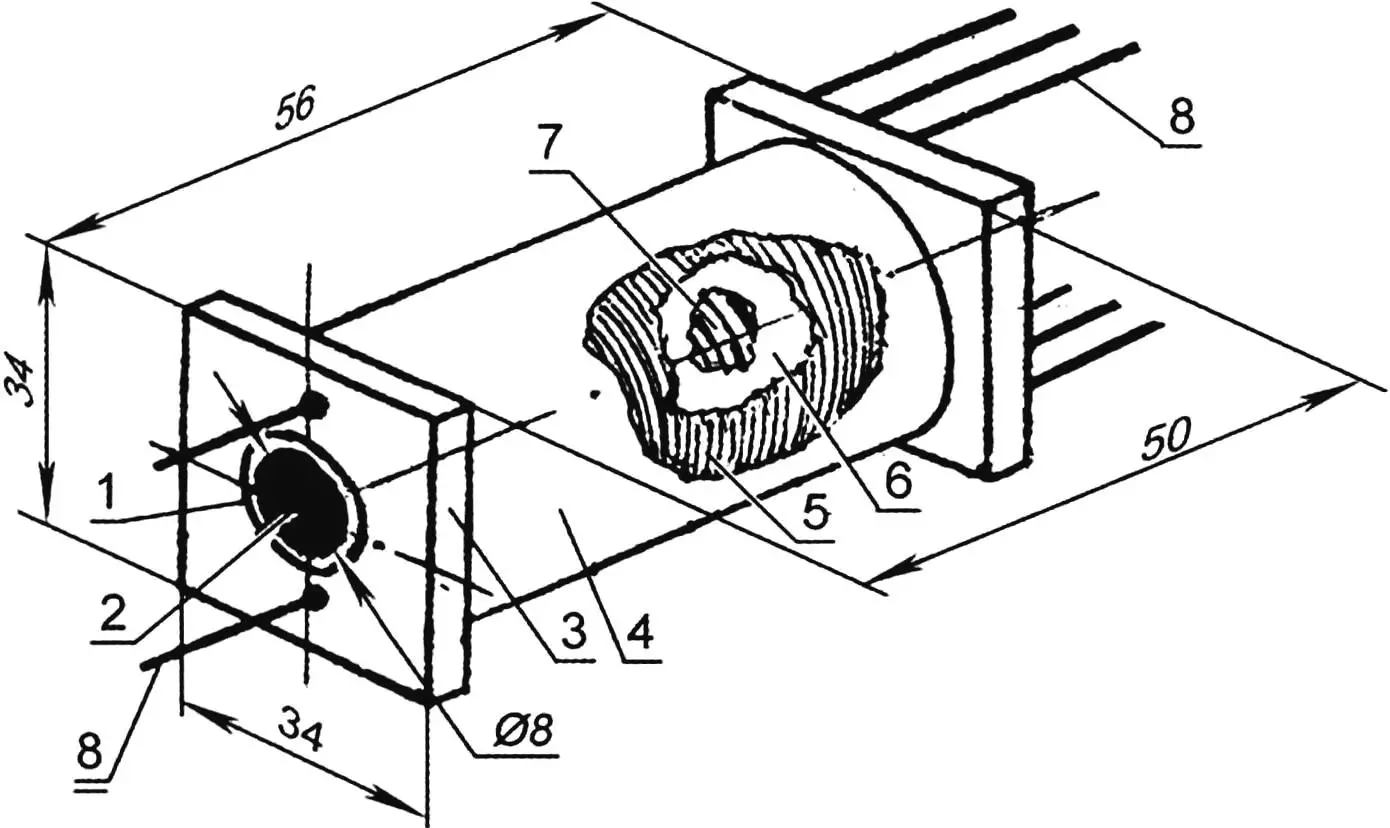
1 — coil former (marker barrel section); 2 — core (from receiver ferrite antenna or turned from TV LOPT ferrite); 3 — cheek (3 mm vinyl plastic or acrylic, 2 pcs.); 4 — protective wrap (glass cloth layer); 5 — high-voltage winding (10,000 turns PEV-2 0.15); 6 — breakdown protection between low-voltage and high-voltage windings (6 layers capacitor paper with epoxy); 7 — low-voltage windings 1 and II (2×14 and 2×6 turns PEV-2 0.5); 8 — lead (15 mm of 1.5 mm tinned copper, 8 pcs.), bend before fitting into case; interlayer insulation — capacitor paper; after every three wire layers — double layer of same paper with epoxy
In the original design, the ESU oscillator was intended for KT818 transistors. Replacing them with KT816 (any letter suffix) and mounting on small plate heatsinks made it possible to reduce the weight and size of the whole unit. The same was helped by using well-proven KTs106V (KTs106G) diodes in the voltage multiplier with high-voltage ceramic capacitors K15-13 (220 pF, 10 kV). As a result, almost everything (excluding the safety whiskers and discharge pins) fits in a plastic soap-dish type case 135×58×36 mm. The assembled protective ESU weighs about 300 g.
Inside the case, partitions of sufficiently strong plastic are needed between the transformer and the multiplier, and near the electrodes on the solder side—both to stiffen the assembly and to avoid sparkover from one part of the circuit to another, and to protect the transformer from breakdown. On the outside, under the electrodes, brass whiskers are fitted to reduce the gap between electrodes and make it easier to establish the protective discharge.
In the author’s design, the spacing between the pin electrodes is 30 mm and the whisker length is 20 mm. A protective spark can form without the whiskers—between the tips of the pins as the active electrodes—but that increases the risk of transformer breakdown and internal flashover.
The whisker idea is borrowed from commercial models. Another adopted solution is to use only a slide-type switch, to prevent accidental activation when the electroshock device is carried in a breast or side pocket.
It is worth reminding radio amateurs to handle the protective ESU with care both during construction and adjustment and when carrying the finished device. Remember that it is intended against aggressors and criminals. Do not exceed the limits of necessary self-defense!
References
1. A. Zhuravlyov, K. Mazel. DC voltage converters on transistors. — Moscow: Energiya, 1974, 88 pp.
2. I. Kaskin. “Galvani-style” protection. “Modelist-Konstruktor”, 1999, No. 5, pp. 15–16.
3. S. Molotkov. Healing ions at home. “Modelist-Konstruktor”, 1997, No. 11, p. 23.
4. V. Chernyshevsky. Electronic stick. “Modelist-Konstruktor”, 1981, No. 1, p. 35.
“Modelist-Konstruktor” No. 2’2012, A. ANTSIFEROV
Recommend to read
 “TOPTUN” — MAT HEALTH
Now even schoolchildren know about the acupuncture — treatment effects on biologically active points located not only on the body, but also on the ears, palms and even the soles of the... HOME SERVICE TIME
Hoping to equip the apartment "talking" for hours, tried to collect an acceptable design using standard domestic circuits. But once faced with the complexities of the "firmware"...
