
 This switch Christmas garlands periodically includes four groups of lamps. The switching frequency can be changed within wide limits by the variable resistor R5 (see diagram).
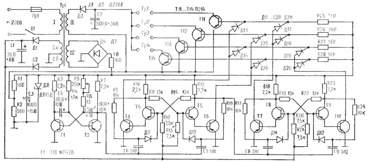
The device consists of multivibrator transistors T1, T2, two triggers with the counting inputs (T3—T10), the decoder on the diodes d13—D20 th four single-stage current amplifier for powerful transistors T11—T14. Garland is included directly in the collector circuit. Each garland consists of ten series-connected lamps 3,5ВХ0,A. 2B of the Electronic switch is powered by AC through a power transformer Tp1. A constant voltage input to the collector circuit of the multivibrator and triggers stabilized by diode D8.
The multivibrator generates clock pulses which switch triggers. Their state of “decode” decoder, the output of which includes transistors T11—T14, administering garlands.
State triggers denote the values “On” and “1”. The first of them corresponds to a condition in which the left (under the scheme) transistor (T3, T4 or T7, TS) is closed and the right opened. Second, on the contrary, left open and right closed.
The initial position of the automatic switching, we assume that when both triggers are in a state of “On”, that is, T3 and T7 are closed. The diodes d13 and Д17 also closed, and negative voltage is applied to the base of T11. The transistor opens and includes a garland Гр1.

Schematic diagram of the automatic switch.
When the multivibrator receives a pulse on the trigger input 1, it goes from state “0” to “1”. The diodes D15, D18 be locked, and the transistor T12 is open: included garland Gr2. Upon receipt of the second pulse from the multivibrator trigger 1 goes back to state “0”. The trigger 11 simultaneously switches to the “1” state. Diodes d14, D19 closed, the transistor T13, and is included garland Гр3. The third clock pulse of the trigger translates both to “1”. Diodes D16, D20 locked. the transistor T14 is opened and the garland Гр4 included. Instead of tube lights suitable led strip light with good illumination. With the arrival of the fourth clock pulse, the shift is repeated.
The device used transistors МП42Б and П214 VST with a factor of at least 20. The data of power transformer the following: core USH 26×28, winding 1 contains 1030 turns of wire sew 0,25 coil 11 and 20 turns of wire of PEV of 0,1 with tap from the middle, winding III — 120 turns of wire sew 0,41, IV winding — 66 turns of wire sew to 0.25.
If the circuit is assembled correctly, the device does not require adjustment.
Recommend to read
 THE SECRETS OF WELDING
"Dear editors of the journal "modelist-Konstruktor"! There is such a difficult craft — the ability to control manual welding. It is necessary not only for professionals in... HEIRS TO THE DESTROYERS
In the 60-ies of XX century the concept of the IUD in the hypothetical third world war Soviet and Western experts met in completely different ways. For example, admirals from the...
