
 Radio, about which we tell, collected under the scheme direct gain works in long ranges (2000 — 740 m or 150 — 400 kHz) and medium (200 — 550 m or 520 — 1600 kHz) waves. Despite its relative simplicity, it has a sensitivity sufficient for admission to the internal magnetic antenna stations, remote distance up to 250 — 300 km With outdoor antenna reception range even more.
The receiver is applied to two circuits: transistor Assembly V1, V2, V5, & К1УС744Б. The latter provides a sufficiently high output power 0.5 W load resistance of 4 Ohms and voltage of power supply 9 V (battery “Crown”). The design has volume controls and tone the upper and lower frequencies.
The ability to “loud” receiving a large number of stations combined with a pleasant timbre and efficiency will make the radio is your constant companion in town trips, tourist trips and on vacation. In addition, the size and weight it is not more spending, but to the receiver it easier to wear to his body, attach the strap (see box).
A high frequency signal, adopted and outlined L1С1 magnetic antenna W1, with the coil L3 when using the separating capacitor C3 is supplied to the base of transistor V1 is the first gain stage of the high frequency. UHF assembled on transistors V1 and V2. Loads of both cascades are the resistors R3 and R6 that are included in the collector circuit. This scheme is evenly stress frequency throughout the range of the received radio waves and significantly reduces the probability of self-excitation of the receiver.
Elements R4, C5 and R7, C8 connected in parallel in circuits of emitters V1, V2, provide the stability of these cascades.
Resistor R8 and capacitor C7 constitute a decoupling filter to eliminate the possibility of self-excitation of UHF through the power supply.
Schematic diagram of the radio.
PCB
Location details
The amplified high frequency signal is supplied to the detector voltage doubler assembled on two diodes V3 and V4. Compared to conventional, odnodolnym, low frequency voltage at the output of our detector is almost two times higher. Therefore, the application of the detector voltage doubler increases the sensitivity of the receiver.
With resistor R9 dedicated low-frequency signal enters the input of the ULF — base of the transistor V5. This cascade is made via an emitter follower. The mode of its operation depends on the value of the resistor R10.
After V5, the low-frequency signal through dividing capacitor C11 is fed to a separate tone control. When moving engines of variable resistors R12 and R14, respectively, change the gain in the low and high frequencies.
Variable resistor R17 is volume control.
Load cascade NCH transistor V6 is the resistor R19, and the V6 mode of operation set by resistor R18.
With V6 of the transistor low-frequency signal through the capacitor C17 is supplied to the output stage is performed on the chip A1. The resistor R21 and the capacitor C18 connected to the circuit negative feedback. The capacitor C20 is a filter element in the supply chain base input of the transistor chip.
Corrective resistor R22 is wound on the frame of the permanent resistor of VS-0,25 konstantinovym or manganin wire Ø 0,1 mm. Suitable for industrial C5-5, C5-16T.
Connected in parallel to a power source G1 electrolytic capacitor C22 prevents the self-excitation scheme in the discharge of the battery.
In the amplifier high frequency and preliminary stages of low frequency applied to the transistors in the chip assemblies К1НТ985А, К1НТ986Б, К1НТ987А or К1НТ987Б. If there are none, UHF can be collected on a regular transistors: П401, П402, П403, П416, П422, П423, ГТ309, ГТ322 with a gain of current TSA≤35. Moreover, the receiver worked steadily gain at V1 must be greater than V2.
RADIO “THE KID” WILL BE YOUR FAITHFUL COMPANION IN THE CAMPAIGN AND FOR THE OUTING AND FISHING. Simplicity, reliability, higher than in batch, output power and sensitivity are the main advantages of this design for integrated circuits.
In the ULF (V5, V6) can be applied to any low frequency transistors, for example, P13, R16, МП39, MP40, МП41, МП42, with a gain of 60-70. Diodes D9 interchangeable on D2.
Constant resistors — MLT-0,25, ULM, ULI; variable resistors R17 SDR-3vm with switch, R12, R14 SP2-2-0,5, SP-0.4 or SDR-9a. Capacitors C3, C4, C6, C10, C13 — KD, KM, C5, C8, C14, C15, C21 — KM or MBM. Electrolytic capacitors C7, C9, C11, C12, C16 — C20, C22, C23 — C50-6. Variable capacitor C1 single-section, KP-180, or from Amateur radio set “boy band.” It is permissible to use one-section two-section variable capacitor, variable capacitor, KPC-3, KPC-5, KTM, KTM-1, KTM-4 from industrial radios “Neva-2”, “Diamond”, “planet”, “Topaz”, “Falcon”, “Gauja”, “Selga”.
The output stage ULF performed on the chip К1УС744Б or К1УС744А (amplifier sinusoidal).
The switch ranges from a children’s portable radio “Baby” or from the voltage regulator ck-1.
Contour coil L1 (ST) and L2 (DV) are wound on a circular ferrite core with permeability of 400 marks with a length of 120 mm, Ø 8 mm, respectively, and contain 75 — 80 and 120-125 turns of wire PEL 0,08—0,1 (better to use Litz wire). The connection coil L3 is 6 to 10 turns of the same wire, wound on a rolling paper frame.
Loudspeaker 0,5 GD-37 or similar type of resistance of the voice coil is about 4 Ohms.
Diagram of the radio is assembled on a printed circuit Board (tab) made of foil fiberglass or Micarta thickness of 1.5—2.5 mm.
Radiator for amp ULF, made from sheet aluminum of 1 mm thickness is attached directly to the PCB.
After Assembly of the receiver to verify the correctness of installation, then turn on the power and check the operation modes of transistors and chips. Magnitudes of currents at the various points indicated on the schematic diagram and are selected with the help of resistors R1, R5, R10, R18. The increase in current consumption is possible due to a malfunction of parts or when the feedback gain stages. The loudspeaker will hear the high pitch sound or a characteristic “gurgling”. Eliminate this unwanted phenomenon by reducing the capacitance of the capacitor CP or increase C7. Good results are obtained by connecting in parallel a power source electrolytic capacitor with a capacity of 50-100 UF.
Tuning into a station, achieve the greatest volume. For reception of distant radio stations connect the outdoor antenna and ground. Then gently move the ferrite core coil L1 and the position of maximum volume of reception are fixed with glue.
The number of turns of the coil L3 when the pick up empirically. Moving it along the rod antenna, to achieve stable operation of the receiver throughout the range. If there is self-excitation, the findings of the L3 should be reversed.
Ranges receiver “adjust” the serving or donativa the turns of the coils L1 and L2.
The dotted lines in the figure marked PCB connections, installation wire.
If instead of microbore applied conventional transistors, their conclusions are soldered into the holes designed for the chip.
A. ROGOVITSKIY Tashkent
Recommend to read
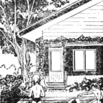 A pool by the porch
A swimming pool, mind you, is too grand a name. In everyday speech, such tiny ponds for toddlers are usually called “frog ponds.” Building one will not take much time or strain your family...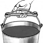 THE HANDLE OF THE WRENCH
For long distance carrying buckets with cement mortar, wire, shackle mercilessly cuts the hand, even if it is in the working glove. Of course, you can wrap the handle of any thickening....
