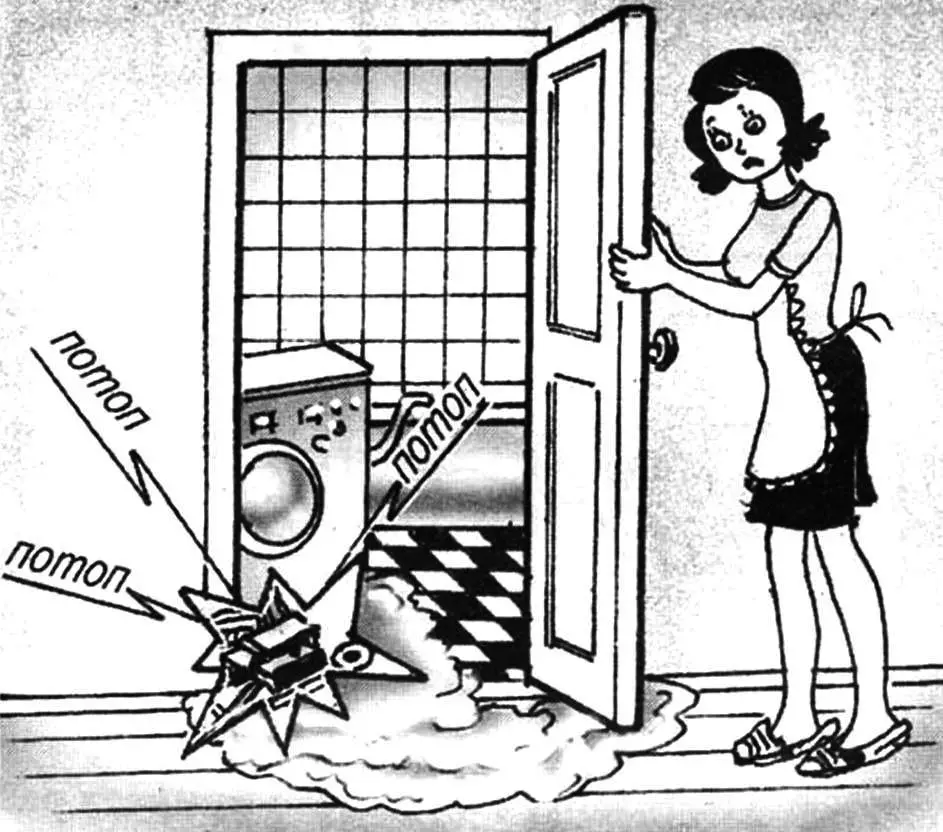
Many families today live in multi-storey buildings and use household washing machines. Anyone who has ever connected such a machine (to the electrical panel and plumbing system) knows how important both of these operations are. In particular, if the drain hose is poorly connected to the apartment’s fan pipes, a leak may occur. This can not only spoil the mood and interior, but also lead to considerable expenses for compensating downstairs neighbors for repairs. Even if the connection is good, it’s recommended to periodically check the clamps securing the corrugated pipe and the drain hose fittings for leaks and tighten them if necessary.
Additionally, leaks can occur in other situations — for example, from above (due to construction flaws), if the apartment is located on the top floor, or due to outdated plumbing elements (pipes, fittings, sink drains, etc.) that have long exceeded their service life. All of these cases threaten to flood the neighbors below, with all the unpleasant consequences.
To avoid such issues, I recommend a simple device — a water leakage detector with adjustable sensitivity over a wide range and an audio indicator. When set to maximum sensitivity, the device can respond even to increased humidity in the air around the sensor. The device’s buzzer emits a loud, intermittent signal of about 40 dB when a dangerous situation arises.
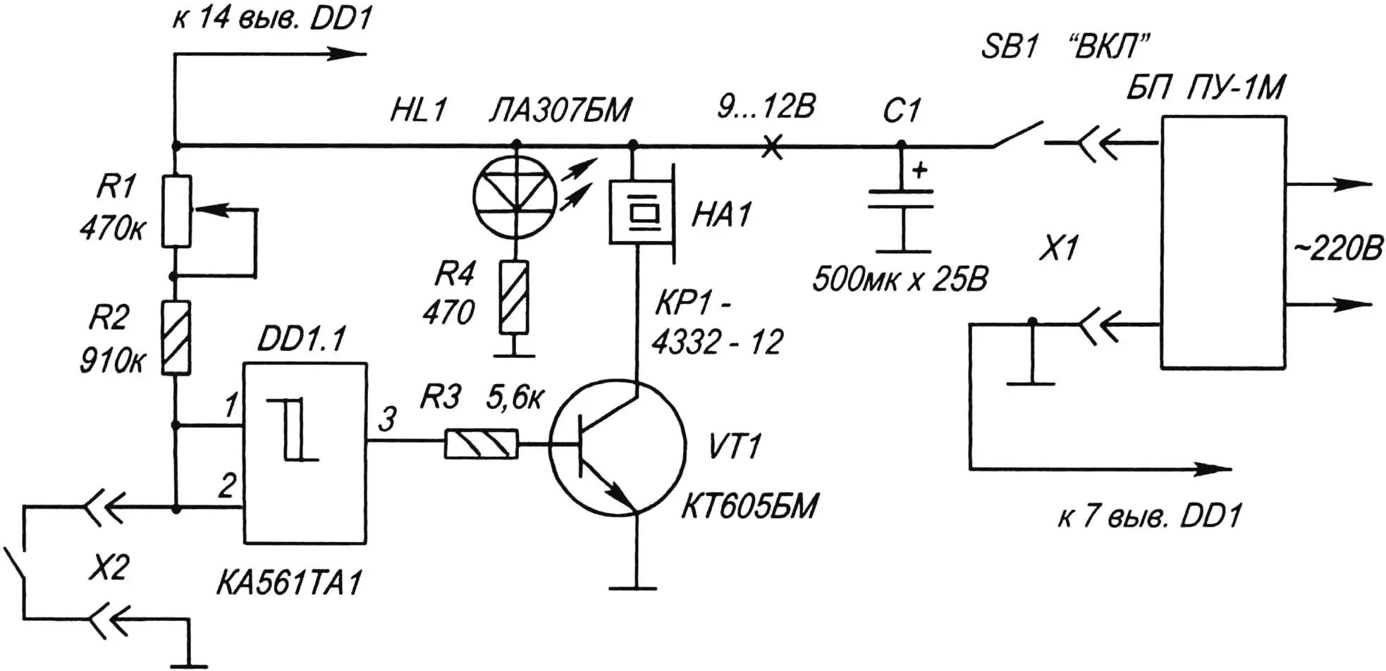
The device is built on the K561TL1 microchip (only one of its elements is used in the circuit). This versatile chip is popular among radio amateurs and offers several advantages over other K561 series chips. The K561TL1 consists of four identical NAND gates with Schmitt trigger transfer characteristics. Each gate features two thresholds — triggering and release. The difference between Uon and Uoff is the hysteresis voltage, which in this case is proportional to the power supply voltage. Thanks to the high sensitivity of the K561TL1 elements, it was possible to create a node that reacts even to minor voltage changes at the input.
A variable resistor R1 is connected between the input of gate DD1.1 and the power “+”, and it adjusts the device’s sensitivity. With the slider at the uppermost position (as shown in the diagram), the sensitivity is at its minimum. As you can see — the circuit is quite simple and could be assembled even by a school student.
The second most important component is the humidity sensor. It is made from a rotation sensor extracted from a floppy disk drive motor (type MS-5301), which was once popular among hobbyists building computers like “Radio-86RK”, “Spectrum”, and others. The motor is carefully disassembled to retrieve the sensor (see Photo 1).
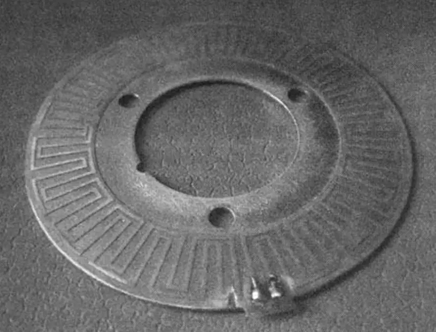
In the photo, you can clearly see that the short-circuited conductive paths arranged in a labyrinth pattern have been cut with a scalpel. This was done to break the circuit. Conductive wires are then soldered to the built-in terminals (clearly visible in the image) using flexible MGTF-0.6 wire. The device and sensor are connected using wires up to three meters long (longer wires were not tested) — they can be twisted pairs of MGTF wire, telephone wire, or other flexible multi-core wires. Only MGTF or similar flexible wire should be soldered directly to the sensor to avoid damaging the tracks on its metal base. After that, the wire can be connected (for example, via a terminal block) to wires of different flexibility and cross-section. At the device end, they are connected to a B2B-XH-A type connector or similar.
Before using, lightly sand the lacquer covering the conductive tracks of the sensor using fine-grit sandpaper.
As long as the sensor remains dry, the input of gate DD1.1 stays high. The output (pin 3 of DD1.1) remains low, and the alarm is off. When slight humidity or water droplets reach the sensor, the input voltage drops, and due to the Schmitt trigger’s characteristic, the gate’s state flips — output pin 3 goes high. This opens transistor VT1 (KT605BM), allowing current to pass through sound capsule HA1 — the audio alarm is activated.
The downside of the device is some delay in deactivating the alarm due to the sensor’s drying time. To handle this, the circuit includes switch SB1, which can be used to manually disable the alarm after detecting and resolving a leak.
If not switched off manually, the device will automatically stop the alarm and return to standby only after the sensor dries completely.
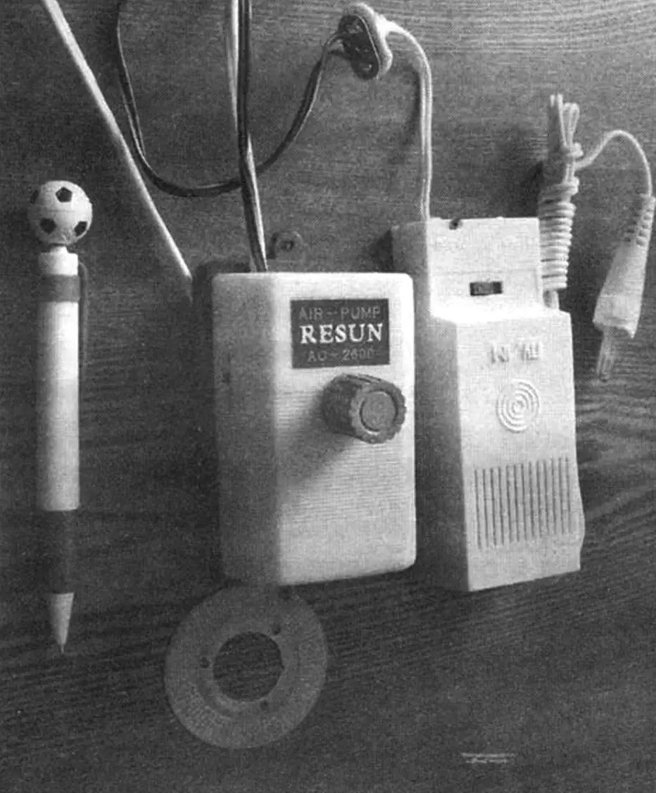
Since this chip type has limited output current (a few mA), a transistor-based amplifier (VT1) is used after gate DD1.1. The collector of this transistor connects to an audio capsule with a built-in intermittent tone generator — model KPI-4332-12, available at radio stores for roughly 20 UAH. The components can be installed in any small suitable case. In the original version, a case from an aquarium air compressor is used. Power leads can be connected via connector X2 (for example, a 6F22 “Krona” battery) or routed through the side hole in the case, as shown in Photo 2.
The device requires no tuning and starts working as soon as power is applied. The sensor should be placed on the floor in a hidden area under the pipes with its contact side facing up. If needed, the wires can be fixed to the floor with insulating tape. Before first use, set variable resistor R1 to the middle position.
To test the system, spray some water near the sensor (within 0.5–1 m) using an ironing spray bottle or similar atomizer. This should be enough to trigger the sound alarm.
As a power supply, the industrial PU-1M unit from the “Severny Press” plant (St. Petersburg) is used. Its output voltage is 9 V or 6 V, selectable via a switch. It features transformer isolation and connects to AC mains. Max load current: 150 mA. Any other power supply with an output of 7–12 V (regulated or not) may also be used.
Be sure to observe correct polarity when connecting the sound capsule with the built-in generator.
The K561TL1 chip can be replaced by K564TL1 or CD4093B. Variable resistor R1 — type SPO-1 or similar, preferably with linear characteristic. Fixed resistors — MLT-0.25 type. Transistor VT1 — KT-605BM, KT603, KT608, KT801, KT815, KT972, 2SC1573, 2N4927 or similar. Sound capsule — any with a built-in generator rated for 5–15 V and up to 100 mA. For example, FXP-1212, FMQ-2015B — these produce a monotone sound instead of intermittent. Capacitor C1 smooths voltage ripple. Switch SB1 is a built-in toggle from the compressor housing, but any miniature toggle like MTS-1 can be used.
Indicator LED HL1 AL307BM is always on — it shows the device is powered and ready. You can substitute any other LED rated for up to 20 mA, such as ARL-5013URC-B.
Obviously, not every radio enthusiast has such a sensor on hand. It can be replaced with a homemade version, such as two metal knitting needles connected with wires. The needles are placed parallel on the floor, about 0.5–1 cm apart, in the likely leak area and taped down. Any flooring material is acceptable.
Additionally, the sensor’s construction can vary. What really matters in this device is the high sensitivity of the chip to even the slightest change in resistance between contacts X1.
A. KASHKAROV
Recommend to read
 INSTEAD OF HEALTH PACKS
Going camping on the bike, bring a little medical band-aid. In the event of a puncture it will replace and glue, and rubber patch. A. CARPENTER, S. Stepanovka, Zaporizka obl. THE CEILING ON A WIRE…
The ceiling today has become a familiar element of the interior and in the office and in the home living room. Want to offer a simplified method of finishing the ceiling lining, which...
