When lighting fixtures and electricity were cheap, the question of a thrifty approach to choosing lighting for stairwells was not seriously considered by anyone.
But life has taught everyone to count every penny, so there’s no need to convince anyone about the advisability of using an automatic stairwell and corridor lighting switch (ASCLS). The question is different: which of the many existing developments should one choose?
In my opinion, the most promising are simple (not “stuffed” with transistors, optocouplers, and microcircuits) ASCLS devices designed for operation under conditions of significant temperature and humidity fluctuations. The proposed schematic diagram of such an automatic switch is accessible even to a beginner, as it contains a small number of radio components and does not require special debugging skills.
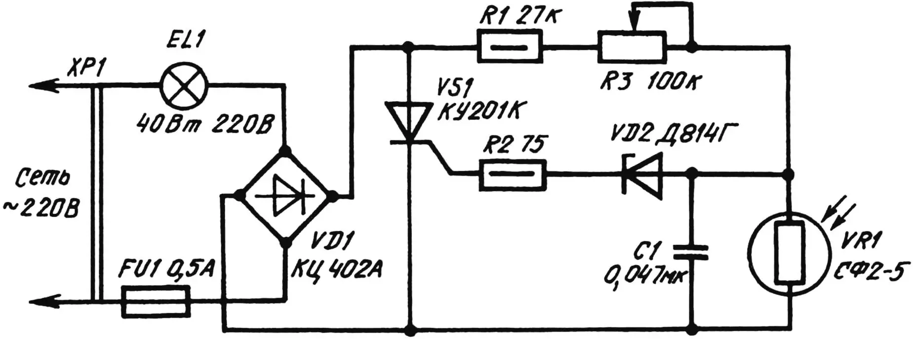
The sensitive element in this circuit is a non-scarce photoresistor VR1 of type SF2-5. Together with resistors R1 and R3, it creates a voltage divider, to which the control electrode of thyristor VS1 of type KU201K is connected through resistor R2 and zener diode VD2.
While the photoresistor is illuminated, its resistance is much less than the total resistance of resistors R1 and R3. Therefore, the voltage across capacitor C1 is insufficient to break down zener diode VD2. In this case, thyristor VS1 is blocked, and the lamp EL1 controlled by the automatic switch is off.
When the illumination of the photoresistor decreases, its resistance will sharply increase and become comparable to the resistance of resistors R1 and R3. The potential on the upper (according to the circuit) plate of capacitor C1 at the beginning of each half-period of the network voltage U applied to the rectifier bridge will begin to rise until VD2 breaks down. The zener diode will open, and the discharge current of capacitor C1 will flow through the control electrode circuit, unlocking thyristor VS1. The automatic switch will transition to the on state, in which it will remain as long as photoresistor VR1 is darkened.
Variable resistor R3 adjusts the trigger threshold of the automatic switch depending on the illumination level.
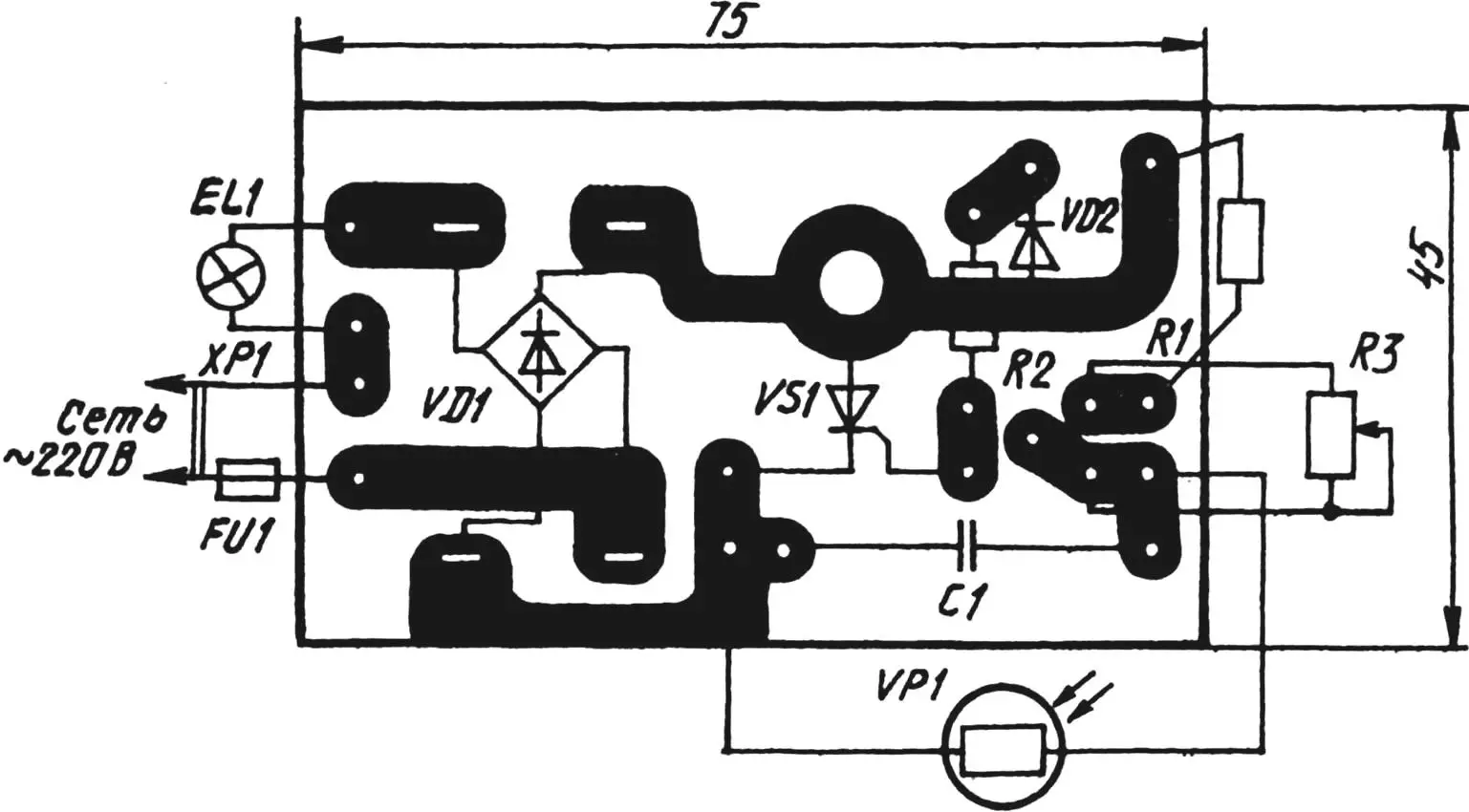
Almost all parts of the homemade ASCLS fit on a printed circuit board made of foil-clad textolite or getinax measuring 75x45x1.5 mm. After assembly and soldering of the automatic switch, the board is coated with protective varnish. A suitably sized plastic soap dish serves as the housing.
Instead of SF2-5, FSD-G1, FSK-1, or FSK-6 can be used in the automatic switch. Moreover, the latter should preferably be placed in a sealed transparent housing.
As a diode bridge, KC402 with any index in the designation or similar semiconductor devices with a reverse voltage of at least 300 V will work. The choice of zener diode is also non-critical: as long as the parameter ΔUst is 10—15 V. Thyristor KU201K can be fully replaced with KU201L or KU202 with a letter index from K to N.
Fixed resistors R1 and R2 can be selected from the MLT-0.5 series, and variable R3—from metal-oxide SP2-3 types. The capacitor is MBM with a rated voltage of 400 V.
Adjusting a correctly assembled automatic switch comes down to setting the sensitivity with variable resistor R3. Moreover, photoresistor VR1 should be positioned so that light from lamp EL1 or street lamps does not fall on it. This prevents false triggering of the ASCLS.
A. UVAROV
Recommend to read
 Power Management Center in the Garage
The proposed development has, of course, nothing to do with space. In this case, PMC (Control Center) is a control center for only the power supply of electrical equipment, not for flights... THE STAGES NOTE
I do karting and would like to share one with those who are interested in this sport. The motor MMVZ-3115 has a weakness — the shift shaft. The fact that the bike's gearshift...
