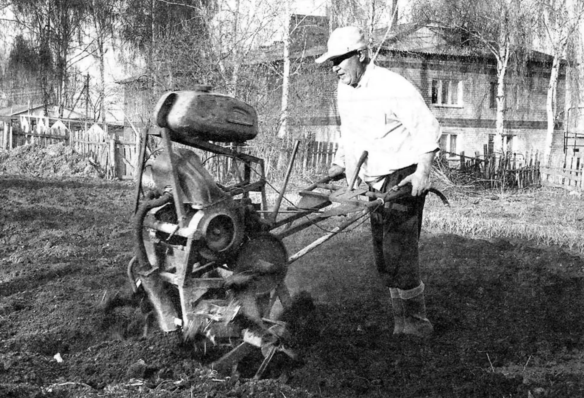
Every year, while digging the soil with my family on the backyard plot where a tractor simply had no room to turn around, I thought:
“I need a motoblock-cultivator.” Of course, I could, by denying myself something else, buy such a mechanism. But, thinking that it would be used only a few days a year, I considered this option unprofitable and therefore unacceptable. And then I decided—I’ll make the motoblock myself!
So that readers don’t judge the creation of my hands too harshly, I’ll say that although I had been nurturing this idea for several years, I made the motorized tiller literally in just a few weeks, before the start of spring fieldwork, from what was at hand. Immediately after making it, I tested the motorized tiller: I completed all the necessary work with its help. And although I myself didn’t like some things about the machine’s appearance, I didn’t redo anything, considering that the main thing in it is still reliability and performance, not attractiveness.
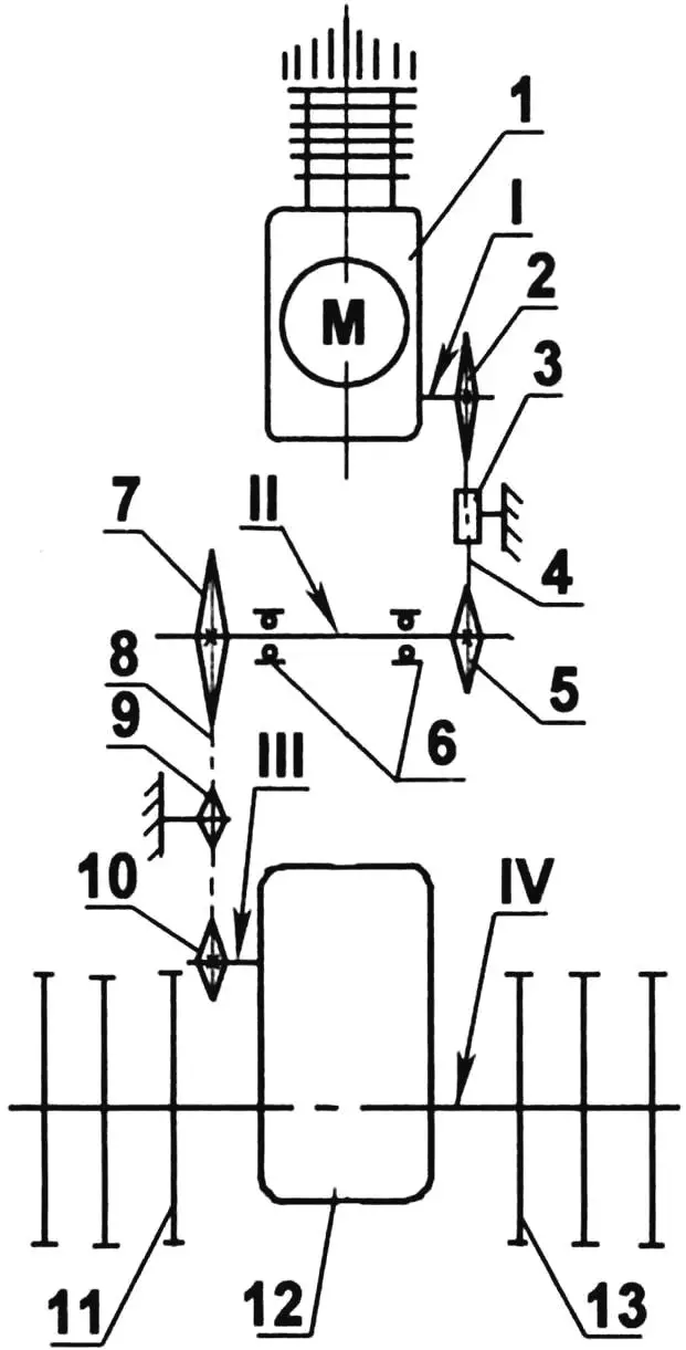
1 — power unit; 2 — output shaft sprocket (z = 22); 3 — tension roller (polyurethane foam); 4 — 1st stage chain (single-row, t = 15.07); 5 — first intermediate shaft sprocket (z = 22); 6 — intermediate shaft support bearings (No. 306); 7 — second intermediate shaft sprocket (z = 15); 8 — tension sprocket; 9 — 2nd stage chain (single-row, t = 15.07); 10 — reducer input shaft sprocket (z = 58); 11 — left cutter block; 12 — reducer; 13 — right cutter block; 14 — motorized tiller control levers;
I — gearbox output shaft; II — intermediate shaft; III — reducer input shaft; IV — reducer output double-ended shaft
The motoblock frame is welded, spatial, of rather intricate (one might even say indefinite) configuration. This happened because I fitted its elements to the layout of the power unit and transmission, and made the elements themselves from the material that was at hand—steel stock of various assortments (angles, round and rectangular tubes, etc.).
I should note that in the drawing I’m providing not a blueprint, but rather a frame diagram with approximate dimensions, since I did much of it “on the spot.”
The upper part of the frame is a kind of subframe-stand for the fuel tank, which I installed above the engine. After all, gasoline flows to the carburetor by gravity.
In the lower part of the frame, on a platform made of steel sheet, the reducer is installed. I positioned the power unit between it (the reducer) and the tank, also resting the bottom of the engine crankcase on the lower ends of the handle levers. Thus, the handles are also part of the frame. The main engine mounting on the frame is on standard brackets, used, like the motor, from an old disabled person’s motorized wheelchair.
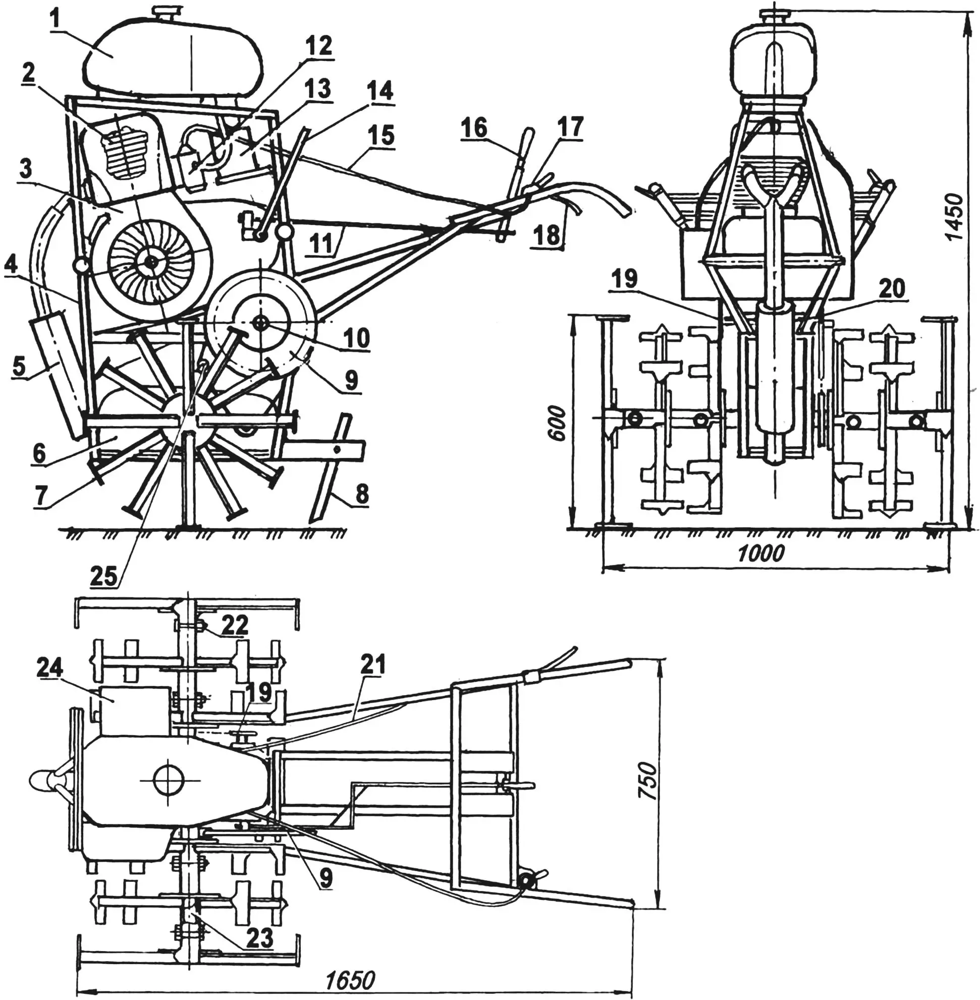
1 — fuel tank (from K-175 motorcycle); 2 — power unit (from SZD motorized wheelchair); 3 — engine forced cooling system (from SZD motorized wheelchair); 4 — frame; 5 — muffler; 6 — reducer (i = 30, from industrial conveyor); 7 — cutter block; 8 — blade-type brake; 9 — second chain drive driving sprocket (z = 58, from agricultural machinery); 10 — intermediate shaft (from agricultural machinery, modified); 11 — speed shift rod (wire Ø5); 12 — carburetor; 13 — air filter (tractor type); 14 — starter mechanism handle (tube Ø22);
15 — carburetor air damper control cable (from motorcycle); 16 — gear shift lever; 17 — throttle adjustment knob (from motorcycle); 18 — clutch disengagement lever; 19 — driven sprocket (from agricultural machinery); 20 — intermediate shaft support housing with two 306 bearings (from agricultural machinery); 21 — clutch disengagement cable (from motorcycle); 22 — pin (M12 bolt, 4 pcs.); 23 — reducer output shaft (round Ø42); 24 — magneto (from DT-54 tractor starter engine); 25 — tension roller
The power unit (engine together with gearbox and clutch) is also taken from an SZD disabled person’s motorized wheelchair. I consider it very suitable for such a machine as a motoblock. First, this engine is unpretentious and runs on low-grade gasoline. Second, it is quite powerful—it has 12 horsepower, and develops maximum power at only 3000 revolutions per minute. Third, its cylinder is equipped with a standard forced air cooling system, without which the engine on a motoblock simply cannot work normally at low speeds.
No modifications to the engine itself were needed, but I had to replace some of its external devices. For example, I made a muffler of my own design for it; installed an air filter from a tractor (the standard one would hardly have provided good air cleaning in dusty conditions); replaced the manual starter handle.
But the main modernization concerned the electrical equipment: I replaced the entire standard set with a magneto from the DT-54 tractor starter engine.
The motoblock-cultivator transmission is combined from different industrially manufactured units and homemade links. Its first stage is the clutch and gearbox of the power unit itself, the second is a homemade intermediate shaft with two chain drives, and finally, the third is a reduction gear.
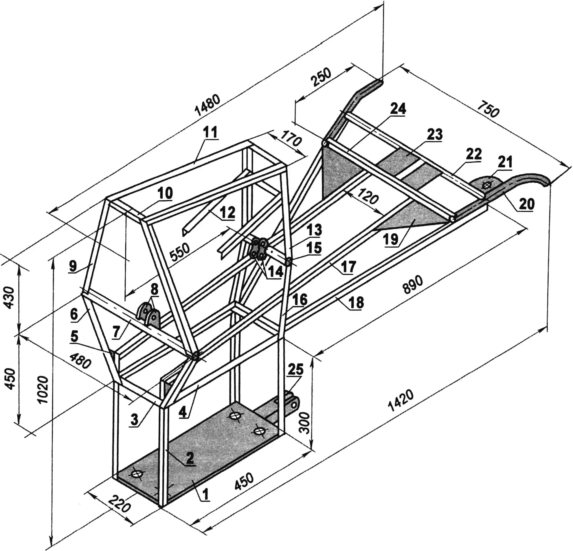
1 — reducer platform (steel sheet s6); 2 — platform post (4 pcs.); 3 — lower cross member (2 pcs.); 4 — intermediate shaft support beam (2 pcs.); 5 — post gusset (steel sheet s3, 2 pcs.); 6 — front lower inclined post (2 pcs.); 7 — front crossbeam (tube Ø44); 8 — front engine mounting brackets (steel sheet s5); 9 — front upper inclined post (2 pcs.); 10 — upper cross member (3 pcs.); 11 — fuel tank support beam (2 pcs.); 12 — air filter support console (2 pcs.); 13 — rear upper post (2 pcs.); 14 — rear engine mounting brackets (steel sheet s5, 2 pcs.); 15 — rear crossbeam (tube Ø44); 16 — rear lower post (2 pcs.); 17 — side member (2 pcs.); 18 — control lever (tube 25×25, 2 pcs.); 19 — lever gusset (steel sheet s2, 2 pcs.); 20 — handle (tube Ø22, 2 pcs.); 21 — throttle grip platform (steel sheet s2); 22 — handle tie (tube Ø22); 23 — gear shift lever mounting platform (steel sheet s2, 2 pcs.); 24 — lever tie (tube 25×25); 25 — drawbar bracket (square tube 70×70)
The first chain drive—from the power unit gearbox output shaft to the intermediate shaft—has driving and driven sprockets with the same number of teeth (22 each), that is, its gear ratio equals 1. The chain is single-row with a pitch of 15.07 mm—from decommissioned agricultural machinery. Its tension roller is turned from polyurethane. The second chain drive—from the intermediate shaft to the reducer input shaft. Here the driving sprocket has 58 teeth, and the driven one has 15, that is, it’s a step-up drive. The chain here is the same, and the tension mechanism is a small sprocket.
Such an atypical gear selection was due to the availability of such parts, that’s first. And second, only this way was it possible with a 30-fold reduction in reducer revolutions to obtain optimal cutter rotation (about 26 revolutions per minute) at maximum power in first gear.
The reducer itself is of industrial manufacture, three-stage with cylindrical helical gears. It’s from a heavy plate conveyor drive, and therefore easily provides transmission of a very large torque.
I replaced the reducer output shaft with a longer (about 1 m) double-ended one (also picked from agricultural machinery), since it simultaneously serves as the drive shaft of the working organs—the cutter blocks.
The cutters are structurally combined into two blocks—12 cutters in each. Each block, in turn, consists of three units—4 cutters each, installed at a 90° angle relative to each other. In addition, the position of the unit cutters in the blocks is offset by 30° relative to adjacent ones, and therefore they work and even move when relocating the block from place to place and on hard ground quite smoothly, at least without jerks.
A cutter consists of a blade made from a 5-mm sheet of tool steel, and a stand made from a steel angle 63×40. The blade is welded to the end of the stand, and the other end of the stand is welded to a flange, which combines four cutters, installed mutually perpendicular, into one unit. The flange, in turn, is fitted onto the block sleeve and welded to it around the circumference.
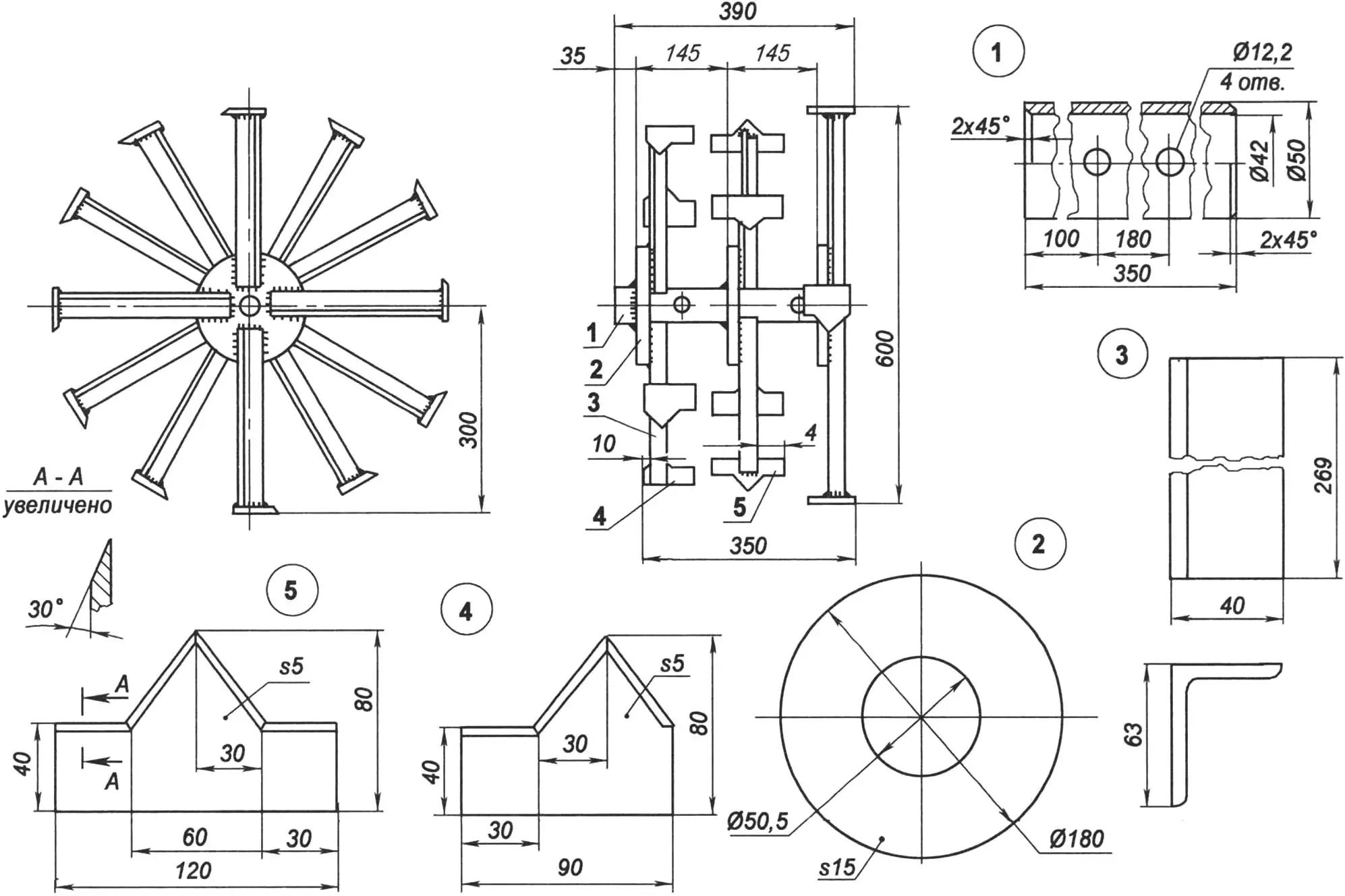
1 — sleeve (tube Ø50×4); 2 — flange (steel sheet s15, 3 pcs.); 3 — blade stand (angle 63×40, 12 pcs.); 4 — extreme left blade, right — mirror image (tool steel s5, 8 pcs.); 5 — middle blade (tool steel s5, 4 pcs.)
The block sleeve is made from a tube whose internal diameter matches (or rather—is slightly larger than) the external diameter of the reducer output shaft (the working organs drive shaft). The sleeve together with the cutter block is fitted onto the shaft and fixed here with two pins made from M12 bolts. The bolt-pins are inserted into holes, previously drilled simultaneously in both parts—the shaft and the sleeve.
The motorized tiller’s operational controls: gear shift levers, throttle adjustment knob, clutch disengagement lever are brought closer to the control lever handles.
The motorized tiller’s speed, in addition to throttle adjustment, is also controlled by a brake stake. To slow down, the stake is driven into the ground using the control levers, and to speed up—it’s raised. The stake is inserted into a bracket, which also serves as a drawbar. A plow or other tillage tool is connected to it—for example, a sweep cultivator shank. In this case, wheels can be fitted instead of cutters. In the wheeled version, the motoblock can work as a cargo trailer tractor, which is also hitched to the drawbar.
I can’t boast of elegance in execution, but the machine works reliably and fully justifies the hopes placed on it in terms of easing labor on the backyard plot and in general in the household.
And although the construction turned out a bit overweight, this is rather a plus than a minus—when using the motoblock with wheels as a tractor, it doesn’t slip on dirt roads even when wet. And when working with cutters, I don’t use the brake so often or fully.
And the cultivator cutters till the soil, as they say, “to a fine tilth,” and the soil no longer requires any further processing (breaking up clods with a shovel, raking, etc.).
V. KURAKIN
Recommend to read
 MILITARY VARIANTS of the Il-12
It is natural that interest to the transport plane, superior in its basic parameters of Li-2, has long mastered the air force showed the military. March 11, 1947 issued a decree of the... ROLE MODEL
The conduct of hostilities rivers are a serious obstacle to the attacking side. Not accidentally during the Second world war, a powerful defensive lines were built on their shores;...
