 (Continued. Beginning in № 9’01). To making a universal charging apparatus, it is recommended to proceed only after at hand will be all you need, including tools and supplies. Case size mm 300x200x200 taken or prepared, as the front panel (300×200 mm), handmade. Transformer power 250 VA, is wound on the magnetic core SHL 50×32 mm (for calculations it is more convenient to use the units of measurement universally accepted Amateur practice, when the cross section of the magnetic circuit is expressed in cm2; in relation to the SHL package recommended core 17.5 cm2). If the core is W-shaped, the sectional area needs to be 1.4 times more, that is, 24.5 cm2.
In any of these cases, the primary winding contains 450 turns ПЭВ2-0.71. In the secondary 32 turns ПЭВ2-2,4 (sh-shaped core requires 37 turns of the same wire). The shielding winding — single layer leads ПЭВ2-0.71.
Try to find a suitable transformer from among the ready — the idea is almost unsuccessful. Partly acceptable only “security forces” from power supply old PC. Existing network winding alteration does not require, in contrast to the secondary, which will have to rewind in accordance with the “specifics of new realities”.
The transformer is fixed in the center of the bottom. It is the hardest detail in the apparatus.
Voltmeter with maximum voltage of 15 or 20 C. you Can use a car from VAZ-2106. However, this instrument has a comfortable separate building, will be subjected to verification by 14.5 In by using more accurate measuring voltage is taken as exemplary. The ammeter needs with a “0” in the middle of the scale and the current total deviation of 10 (5+5) or 20 (10+10) A. Car talismanically use is undesirable because of their inherent large error indications.
The wires between the external shunt and the measuring head should not be changed, video calibration. Relay — compact car, like 90.3747. Radiators for installation of the diode VD1, thyristor VS1 must have a radiant heating surface of 300 cm2 each, and for the transistor VT12 with an area of 650 cm2 — standard finned or needle. Switches SA1, SA2, SA3, you can use any which is suitable for use as a network switch. The buttons you only need one pair of normally closed (SB1) and open (SB2) contacts.
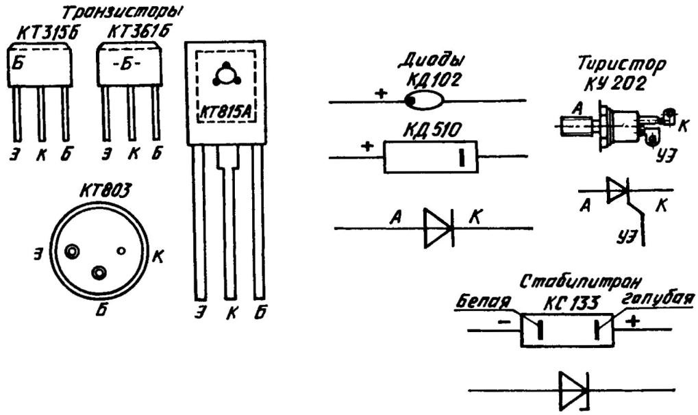
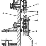
The Pinout of the used semiconductor devices
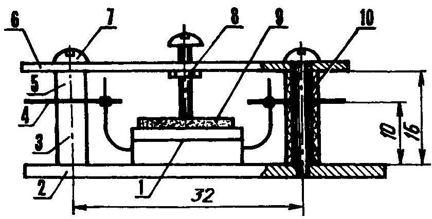
The node of the diode KD213:
1 — the diode; 2 — radiator; 3 — the insulator (2); 4 — pin petal (2 PCs); 5 — bushing-insulator (2); 6 — plate; 7 — the screw M3 or M4 (3 PCs); 8 — nut; 9 — plate-heat sink (Ø10 circle); 10 — PVC pipe (2 PCs.)
Variable resistors R2, R20 wire PPZ or their analogues. The main thing for these electronic components, the nominal resistance (safety pads only affect appearance). The rest of the “things” — according to the circuit diagram and the PCB. During installation, special attention should be paid to the correct polar connection of electronic components.
For mounting the diode VD1 is required, two insulating stand. In the absence of racks it is possible to use a hard plastic tube with a height of about 10 and 5 mm and the petals to hold the wires. The screw to put PVC pipe on top of the short rack, then two petals and the long counter. All this is mounted on the radiator. The petals are isolated and rigidly fixed.
Setting КТ803 (VT12), it is necessary to isolate the findings of the emitter and base of the radiator. PVC pipe to put on the wire before soldering, and then pull up inside the radiator (to the transistor case). For Assembly of all heat sinks, it is recommended to use a sheet of heat resistant plastic, the length of which must correspond to the dimensions of the housing. Radiators are under stress, and therefore should not have a galvanic connection with each other.
The plastic sheet must be secured vertically within the housing, at a distance of 4-5 cm from the back wall, which protects the radiators and they are items from foreign metal objects. The ribs of the heatsink should be vertical, and the items, if possible, at the bottom for better cooling.
On the front panel is the maximum number of external components. It is the organs of control and indication. They are grouped by purpose. The NETWORK switch, fuse 2 A, light EL1 serving as indicator on located in the lower right corner, and switch the CYCLIC-DUTY, 10-amp fuse in the left. In the middle of the down — output terminals “+” and “-“.
In the upper left corner is fixed the ammeter PA1, in the right — voltmeter PV1. The current controller of the charge and a button CHARGE should be around. Symmetrically, they should place the regulator the discharge current and DISCHARGE. In the center of the front panel clock. It is necessary to consider that indicators of HG1—HG3 are not located strictly in the middle of hours, but because when you install the latest you need to be slightly offset relative to the center panel. In addition, the necessary 3-4 mm gap (with the obligatory strip of cardboard between the panel and motherboard).
The location of the resistors R25— R29 — on the bottom of the apparatus. There should be for them to install four insulating stand. So much so that watt resistors form a rectangle with the dimensions of 80×30 mm. the racks must be soldered to two thick wire with a diameter of 3-4 mm with a length of 80 mm. And on the wires to solder the resistors. It is in this installation and provides maximum airflow resistors cold air from under the machine.
Toggle switch EMERGENCY CHARGE – back or on the flat plate radiators, even if the place is hard to reach. This is the seldom-used switch. We can only wish to never had to use it in.
Circuit Board manufacture is the most complex process, particularly for people without relevant experience. You must redraw the drawing boards on notebook sheet in the box. You then stick the sketch, the resulting life-size, foil on the PCB or Micarta (even soap) and start drilling holes. Diameter of drills: 0.8 mm (under output terminals) and 1.0 mm (the resistors R14, R15 and thick the findings of the Zener diodes). Still need the drill bit diameter 3.2 mm (for screws for fastening the Board).
After drilling the holes you should clean the surface of the future Board with fine sandpaper and not touching the foil sides with your hands, draw tracks napolcom, mindful of the fact that copper is best seen green. You can use a pen or a poster pen. And when the varnish is dry the pattern is to be cut with a knife inaccuracies and blots. If you need to paint the revealed flaws and again to clean up all the “Rasplavy”.
Making sure that the future pattern of conductive paths corresponds to a sample, it is possible to etch the Board. In a shallow ditch (not metal) to dissolve the ferric chloride at the rate of 50 g per 0.5 liters of water, enough for two boards. The water should be slightly warm, because when you add ferric chloride will start to self-heating of the solution, and quite strong.
Tied to the drilled corner thread, the cost dipped in the solution. Etching takes about 30 minutes. All this time, gently shake the cost. You can even periodically take it out for a quick washing off of plaque or by typing the solution through the needle into a disposable syringe, is not very strong jet every 5-10 min to pour the etched pattern, seeking to open from the varnish sections of the boards were not even traces of copper.
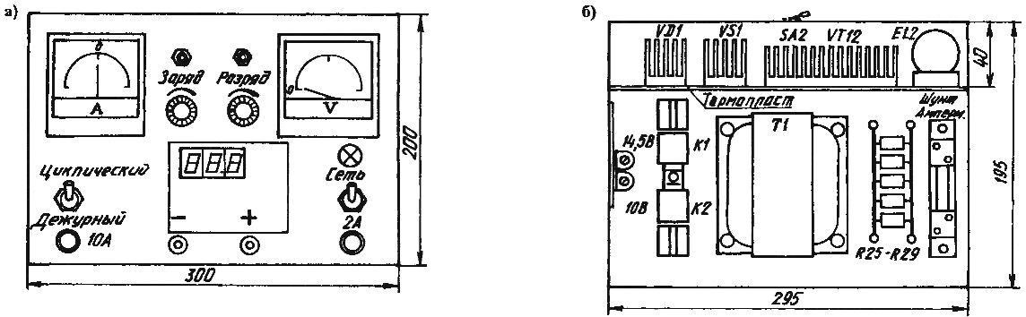
Front panel (a) and the location of the radio components on the bottom (b) of the apparatus
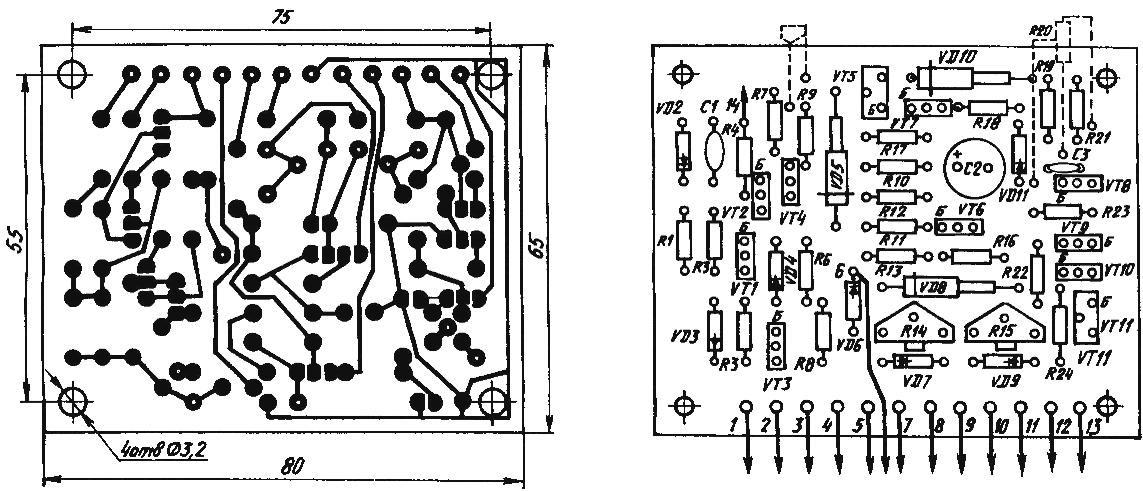
PCB charging device (unit of the electronic clock is not shown) and the location of the radio components
Followed by rinsing and drying the Board. The remnants of varnish on the tracks and remove (with simultaneous scraping of the contact pads for tinning) sandpaper.
Installation of components on the Board doing so is to never be wrong. In order to simplify and avoid confusion, you can use the colored wire in PVC insulation.
A little about replacements. Instead of the semiconductor valve KD213 acceptable to use two D245 (or 10-amp analogues). The rest of the diodes — any silicon (KD). However, we should not forget that through VD6 will leak while working 60-80 mA. So as of this semiconductor device, it is desirable to use КД102, KD510 or similar to current (about 100 mA) of the diodes.
КТ803 transistor can be replaced by КТ819 and KT315 and KT361 it is better to use letters B, G in the marking. The capacitor C2 100 µf (acceptable and for larger capacity, but would fit on the Board) with an operating voltage of 10 V. Instead of MLT will fit any other small resistors. Relay 90.3747 is replaced by 113.3747 with the addition of copper or bronze (brass) lobe for the attachment.
Adjustment is not the switching threshold of the control unit. Pre-need to prepare two rechargeable batteries (charged and discharged to 10.5 V), otherwise the debug and setup of equipment will take more than one day.
You must first install the trimmer resistors R14 and R15 b middle position. Then connect the discharged battery to start the discharge. The terminal voltage should quickly drop to 9.7—9.8 V (when the load is removed the battery voltage rises to 0.5—1 In).
Rotation of the resistor R15 clockwise to turn off the CATEGORY mode. EL2 light bulb (headlight) goes out. If the machine will switch early, turn R15 clockwise (contact to displace 1-2 mm). Then recharge the battery for few seconds and again turn on the DISCHARGE. Following this, the device itself should go on a CHARGE. If the switching voltage does not match the installed, to correct it. To check the switching threshold several times.
Now connect the charged battery, pressing the SB2 button again to switch the device mode CHARGE. Verify that a charged battery will quickly gain the required rotation of 14.5 V. a resistor R14 clockwise to turn off the CHARGE. Thus the lamp EL2.
Similarly, after a few seconds, it should re-enable the CHARGE and control: at what voltage the control unit automatically switches to the DISCHARGE. If necessary, repeat the adjustment.
After the incorporation of the electronic clock, the machine is ready to work.
S. KHRISTOFOROV, Yoshkar-Ola
(To be continued)
Recommend to read
 COMPOTE ETERNAL COVER
Snowy and cold winter you open a jar of homemade compote — like and release the aromas of hot summer and autumn generous. But do not rush to throw out warped opener metal cover — can be... OH, THE SLEIGH – RIDE THEMSELVES
Perhaps, in the memories of every adult baby winter fun be sure to contact the sled. And it's safe to say that in a rare home today will not meet them: they still serve the kids and...
