
 Sometimes the output current in the power supply can be increased up to a critical value (due to the increase of power consumption, faulty connections or load devices), which will inevitably lead to the accident consequences of overload can be significant and even irreparable if you use a power supply without the security host (like today often make hams, making simple sources and buying cheap adapters) for Example will increase power consumption, can lead to failure of network transformer, it is possible to separate fire elements and odor.
In time to notice the power supply output limit mode, set simple the overload indicator Simple because they usually contain only a few elements, inexpensive and available to Set these indicators in almost any homemade or industrial power supply is rather simple electronic circuit indicator overcurrent figure 1.
It is versatile and can be applied in power supplies and regulators with different output voltages (tested at a voltage of from 5 to 20 V) Work items based on the fact that after series with the load in the output circuit of the power supply includes a limiting resistor of small resistance (R3 in the diagram). In this case, the values and the component values selected for a power source with an output voltage of 12 V, Respectively, in order to expand the range of effective application of the proposed display unit, you will need to change the parameters of the elements R1 — R3, VD1, VD2 Until no overload, power supply (and load unit) is operating normally, through R3 flows allowable current and voltage drop across the resistor is small (less than 1 V) is Also small in this case, the voltage drop across the diodes VD1, VD2, and HL1 led is barely lit.
Increasing the current consumption in the load or short circuit between points A and B the current in the circuit increases, the voltage drop across the resistor R3 can reach the maximum value (output voltage of the power source), resulting in HL1 led lights (blinks) in full force and effect For a visual effect applied in circuit flashing led L36В It can be replaced with a similar electric characteristics of the devices, e.g., L56В, L456В (high brightness), L816ВRС, L769BGR, TLBR5410 etc.
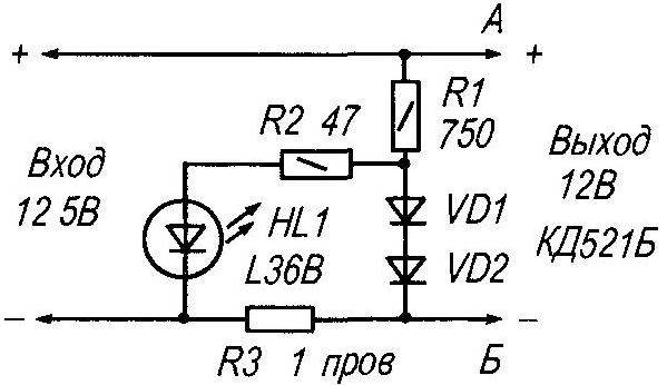
Fig. 1. Schematic wiring diagram indicator light overcurrent
The power dissipated on the resistor R3 (in the short-circuit current), more than 5 watts, so the resistor is made independently of the copper wire PEL-1 (PEL-2) with a diameter of 0.8 mm (it can take from unnecessary transformer) stationery a pencil wound eight turns of the wire, the ends served, and the pencil is removed Wirewound resistor R3 is ready.
All fixed resistors type MLT-0,25 or similar Instead of the diodes VD1, VD2 (КД521Б) is acceptable to establish KD503, КД509, KD521 with any alphabetic index They protect the led in overload (dampen excessive voltage).
Unfortunately, in practice it is impossible to constantly visually monitor the status indicator led in the power supply, so it is wise to complement the circuit of electronic hub sound This circuit is shown in figure 2.
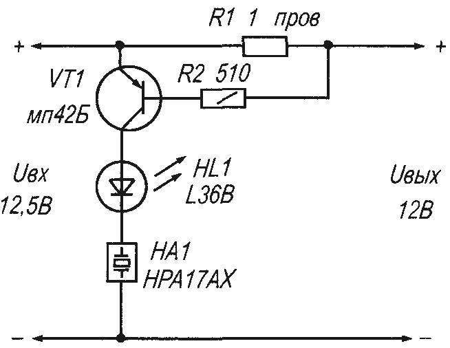
Fig. 2. Schematic wiring diagram of the host sound and light overload indicator
As you can see, it works on the same principle, but unlike the previous, this device is more sensitive and the nature of its work due to the opening of the transistor VT1 when establishing its database of potential over 0.3 V At VT1 implemented current amplifier Transistor of the selected germanium — from the old days of Amateur radio It can be replaced by the same electric characteristics of the devices МП16, МП39-МП42 with any alphabetic index In an extreme case, is possible to install the silicon transistor KT361 or КТ3107 with any alphabetic index however, the turn on threshold of the display will be different the Threshold of the transistor VT1 is dependent on the resistance of the resistors R1 and R2 and in this scheme, when the power source voltage of 12.5 V display will turn on when the load current exceeds 400 mA.
In the collector circuit of the transistor included flashing led light and a cap with a built-in generator CC NA1 When the resistor R1 a voltage drop of 0.5 reaches 0.6 V, the transistor VT1 opens, led HL1 and the capsule NA1 receives the supply voltage As a cap for the led is an active element limiting the current, operation mode of led: steady Thanks to the use of flashing led capsule will also sound intermittently, the sound will be heard during the pause between flashes of the led.
In this scheme it is possible to achieve an even more interesting sound effect if, instead of capsule NA1 to turn on the device KPI-4332-12, which has a built-in generator is interrupted So the sound in case of overload will remind the siren (this is facilitated by the combination of the interrupt led flashes and the internal capsule interrupts the HA1 a sound loud enough and effectively (heard in an adjacent room with an average noise level) will attract people’s attention.
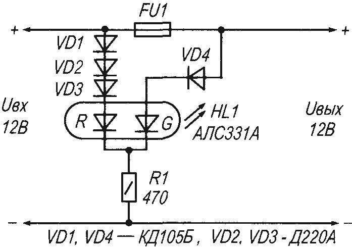
Fig. 3. Indicator light the fuse blows
In those constructions, where the fuse is installed (or other, e.g., resettable) fuse is often required to visually monitor their work diagram of the device shown in figure 3, allows you to do this we applied a two-colour led with a common cathode and, accordingly, the three leads Who in practice had the diodes knows that they are functioning somewhat differently than expected it would Seem that green and red should appear on the led in a common housing, respectively, in the application (in the right polarity) voltage to respective conclusions R or G But it is not so While the fuse FU1 intact, to both anodes of the led HL1 applied voltage Threshold of illumination is adjusted by the resistor R1 If the fuse interrupts the power circuit of the load, the green led goes off and the red remains to Shine (if power is not lost) Because the permissible reverse voltage for LEDs is small and limited, for the specified design schema is introduced diodes with different electrical characteristics VD1 —VD4 that the green led consistently included only one diode, and to the red three, is due to the characteristics of the led АЛС331А, seen in practice In the experiments it was found that the threshold turn-on voltage of the red led smaller than a green to counterbalance this difference, and put a different number of diodes.
If the fuse to the green led (G) a voltage is applied in reverse polarity, the component Values in the circuit for this voltage control circuit 12 Is led АЛС331А permissible to use other similar devices, for example КИПД18В-M, L239EGW.
A. KASHKAROV, St. Petersburg
Recommend to read
 “STAYERS” BLUE AQUADROME
We offer modelers design developed and successfully tested Czechoslovak athletes. The basis for its design was the model class F1E, with which the author is an engineer Ow. Valens was in... THE AMPHIBIAN ON THE ICE TRACK
The prototype model has served as a snowmobile amphibian created in 60-ies a group of young professionals under the leadership of the Soviet aircraft designer A. N. Tupolev. This car...
