I propose a design for a gasoline-electric unit (GEU) “Firefly”, designed for charging batteries, powering lighting lamps and other DC consumers at 12 V.
I developed this unit three years ago at the request of my friend, an avid hunter and fisherman. Since then, “Firefly” has been serving reliably, lighting his taiga cabin and helping him with household chores.
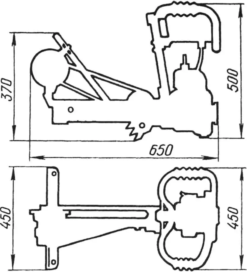
Relatively small dimensions and weight, economy, reliability, as well as the possibility of quick transformation into a chainsaw — these qualities of the GEU are attractive not only to hunters, but also to foresters, loggers, fishermen, and geologists.
The GEU is very simple to manufacture. It is assembled mainly from available components and parts of the “Druzhba” (or “Ural”) chainsaw and consists of the following main parts: engine with reducer, frame, generator, control panel and connecting cables.
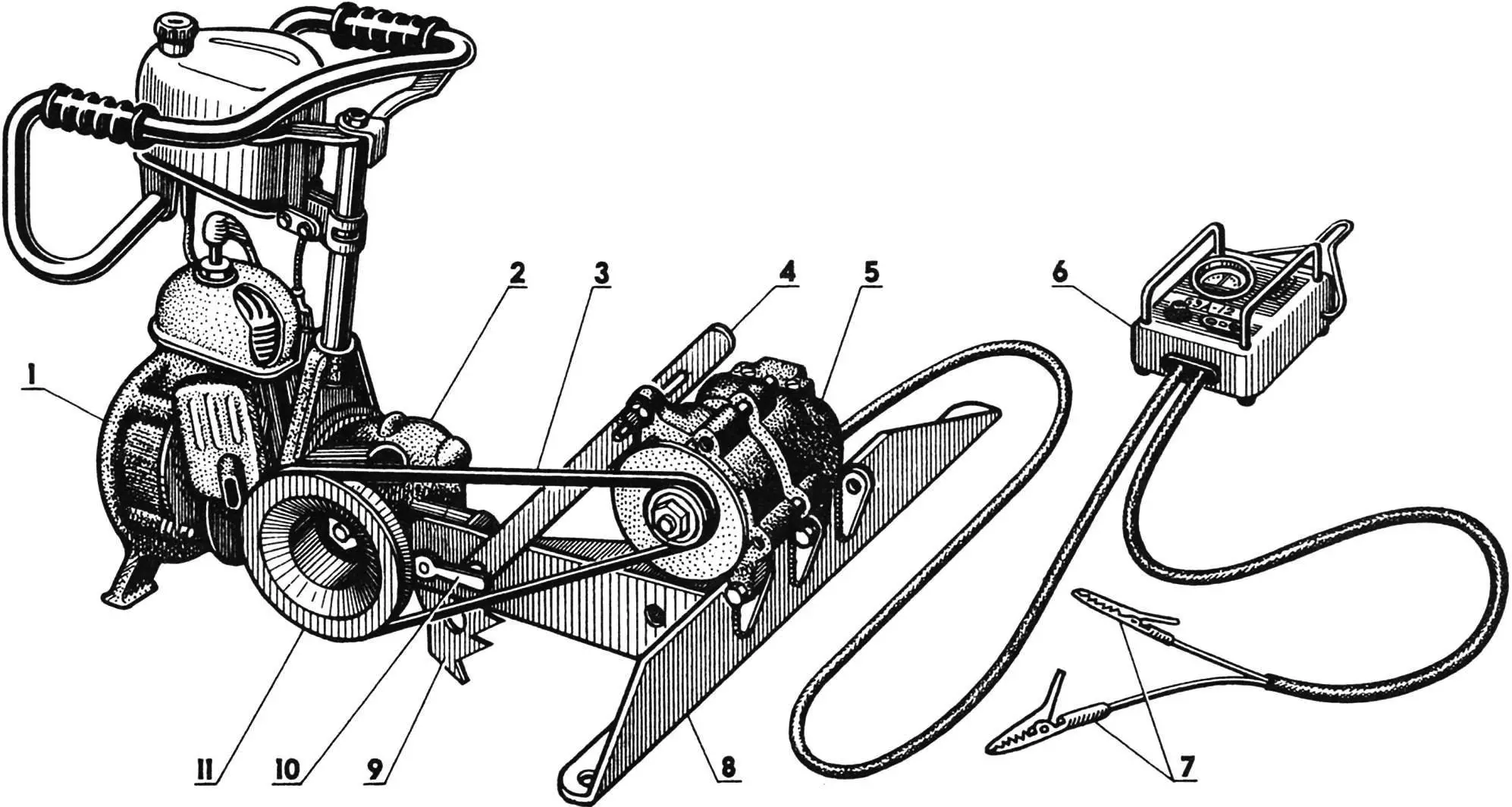
1 — chainsaw engine “Druzhba” (or “Ural”); 2 — reducer; 3 — V-belt (1018x10x8.5); 4 — adjustment bar; 5 — generator G-250; 6 — control panel; 7 — “crocodile” type clamps; 8 — frame; 9 — saw toothed stop; 10 — nut with handle for mounting frame to reducer; 11 — replaceable drive pulley
The frame is a welded structure. A part of the saw bar from a faulty chainsaw is used as the longeron. An M10 nut for the bolt securing the lower end of the adjustment bar is welded to the oblong mounting hole of the longeron on the left side. The upper end of the bar has a slot that allows rotating the generator and thereby tensioning the V-belt. The longeron connects to the engine reducer in the same way as the standard saw bar of the chainsaw.
A cross member made of angle iron with a cross-section of 63x40x5 and a length of 450 mm is welded at a 90° angle to the longeron. Two holes with a diameter of 10.2 mm for bolts are drilled in the ends of the small flange of the angle iron, which can be used to rigidly mount the GEU on an additional base — a thick board, beam, log, etc. The connection of the longeron with the support angle is reinforced with a steel gusset plate 1.8 mm thick. A stop profiled in accordance with the reducer crankcase protrusion is welded to the apex of the gusset. Holes with a diameter of 6.1 mm for cable clamp bolts (or relay-regulator in case of its installation) are drilled in the gusset. Three brackets for mounting different types of generators are welded to the outer side of the stop angle.
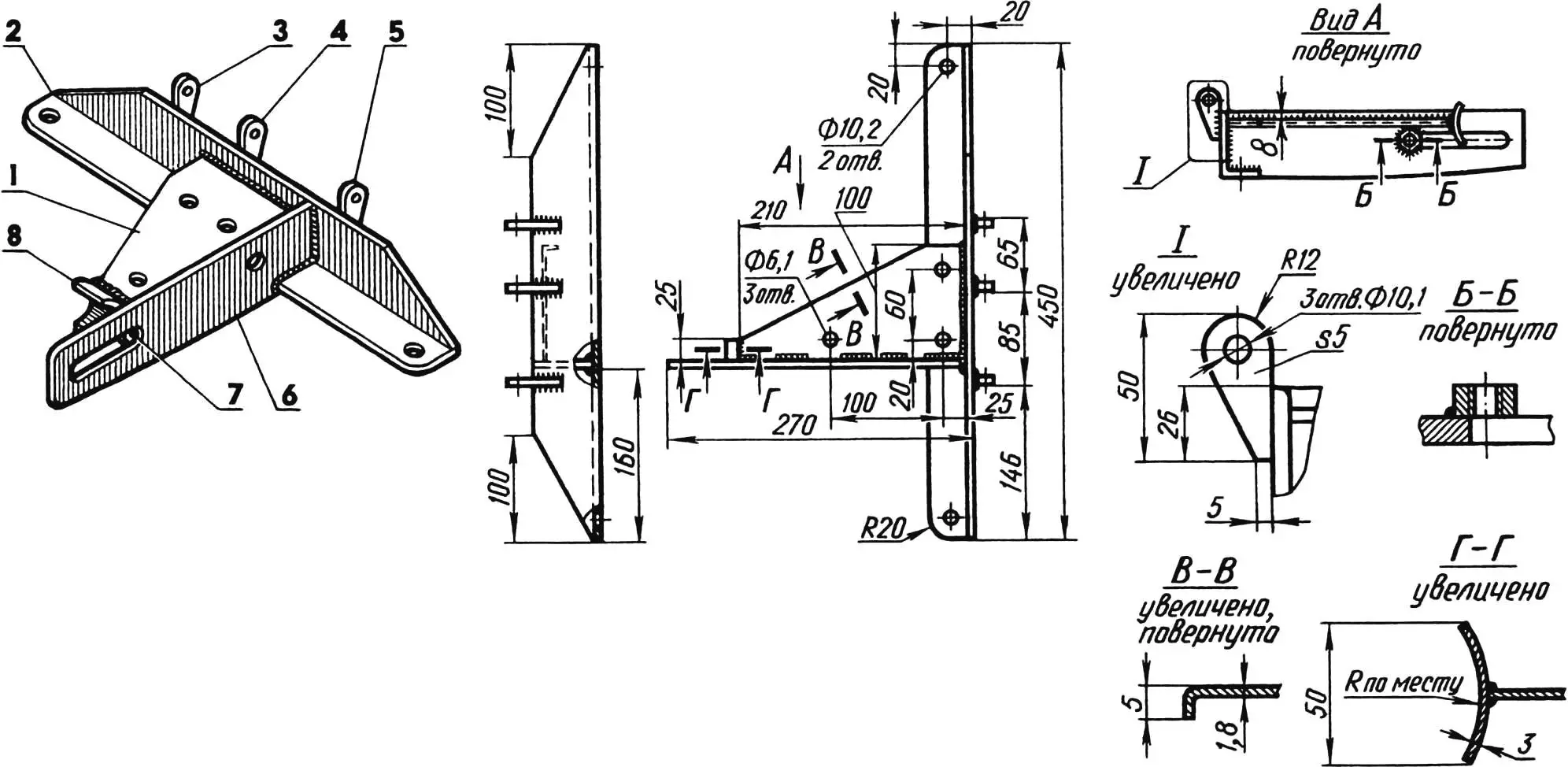
1 — gusset (sheet s1.8); 2 — cross member (angle 63x40x5); 3 — generator G-21 mounting bracket (strip s5); 4 — generator G-250 mounting bracket (strip s5); 5 — common generator mounting bracket (strip s5); 6 — longeron (part of chainsaw bar); 7 — M10 nut for adjustment bar mounting; 8 — stop
After completion of locksmith and welding work, the finished frame was primed and painted with black automotive enamel.
The drive pulley is taken unchanged from the fan drive of the GAZ-53 engine. It is attached to the hub with four M8 bolts. The hub is homemade, using the splined part of the standard drive sprocket of the chainsaw chain drive.

The hub is made as follows. On a lathe, the teeth of the standard sprocket are ground so that a cylinder with a diameter of 30 mm is formed in their place. A flange — a ring with a thickness of 14 mm and diameters of 69 mm (outer) and 30 mm (inner) — is turned separately; chamfers of 3×45° are removed along the inner diameter. Then the sprocket cylinder is pressed into the ring and welded along the chamfers. The resulting hub blank is turned to the dimensions shown in the figure, and threaded holes for mounting the pulley are drilled in it.
All electrical devices are mounted in the control panel housing. An ammeter for 20 A current, switch V-45, socket for connecting DC consumers and holder DPK1-1 for a 15 A fuse are brought out to the front panel. The relay-regulator RR-350 is attached with two M6 screws to the panel cover from inside. Mounting wires — with a conductor cross-section area of 2.5 mm2.
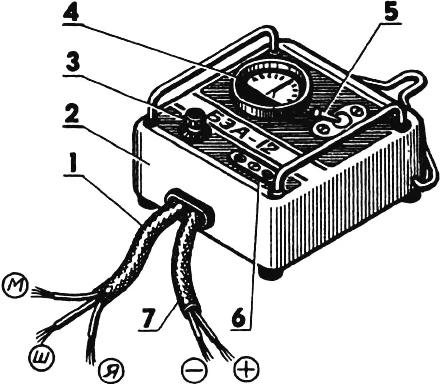
1 — generator connection cable; 2 — housing; 3 — fuse holder; 4 — ammeter; 5 — switch; 6 — socket; 7 — battery connection cable
The mounting electrical circuit of the GEU is part of the GAZ-53 vehicle electrical equipment circuit.
Before mounting the devices, the housing was cleaned with fine-grained sandpaper, degreased with gasoline, primed and painted with black automotive enamel. After drying, all necessary inscriptions were applied to the front panel using stencils and white enamel.
The housing has a cover made of 1.8 mm thick steel at the bottom. It is attached with M5 bolts with rubber bushings on the heads, which serve as supports for the panel on a horizontal surface. The panel can also work in a vertical position, for which it has a hanging loop, hingedly connected to the housing.
The devices are protected from accidental mechanical damage by two brackets made of 5 mm diameter steel rod, installed on the front panel of the panel on the left and right.
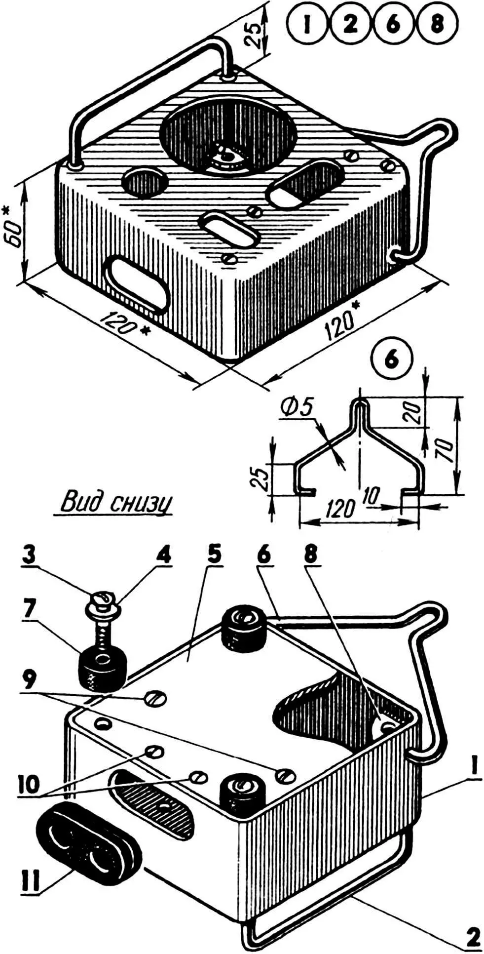
1 — box (steel, sheet s1.5); 2 — protective bracket (steel, rod Ø5, 2 pcs.); 3 — M5 screw (4 pcs.); 4 — washer (4 pcs.); 5 — cover (steel, sheet s1.8); 6 — hanging loop (steel, rod Ø5); 7 — support (rubber bushing Ø20x10x5, 4 pcs.); 8 — cover mounting shelf (steel, sheet s1.8, 4 pcs.); 9 — M6 screws for relay-regulator mounting; 10 — M5 screws for cable clamp; 11 — cable entry (rubber)
“Firefly” is equipped with flexible connecting cables of the KRPT brand. They have a length of 2—2.5 m and a conductor cross-section area of 2.5 mm2. The working leads of the cable connecting the control panel and the battery being charged are equipped with “crocodile” type clamps with markings “+” and “-” signs.
A cable entry — a bushing made of thick rubber — is inserted into the side hole of the panel housing. Brass terminals are soldered with tin to the ends of the mounting wires of the cables, and additional insulation made of polyvinyl chloride tube segments is put on.
Operation of the gasoline-electric unit is very simple.
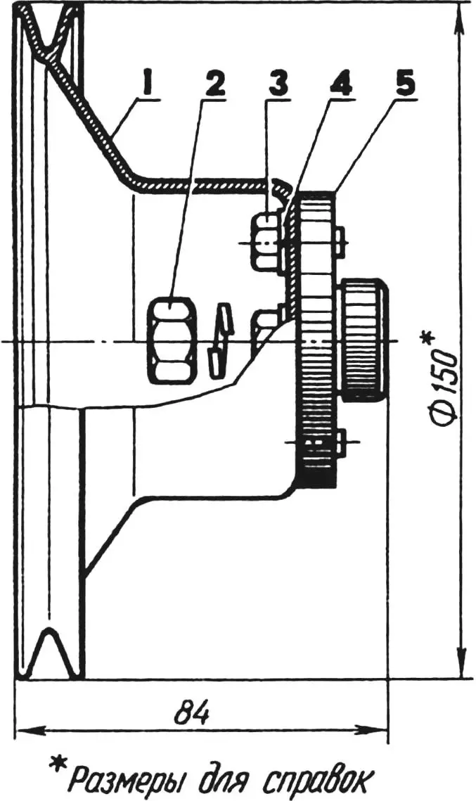
1 — pulley (from GAZ-53 engine); 2 — shaped nut M14; 3 — M8 bolt (4 pcs.); 4 — spring washers (5 pcs.); 5 — hub
The chain, saw bar and chain drive sprocket are removed from the chainsaw, and the GEU frame is attached to the reducer crankcase with the longeron. A replaceable drive pulley is put on instead of the sprocket, and the V-belt tension is adjusted. This completes the transformation of the chainsaw into a GEU — and it is ready for work.
If it is required, for example, to charge a battery, it is connected with a cable to the control panel, observing the polarity of the “crocodile” type clamps. Then the engine is started. After the generator is excited and current appears (this will be shown by the ammeter), the crankshaft speed necessary to obtain the power consumed by the battery is set with the adjustment screw. The moment of completion of the charging process is determined, as usual — by the ammeter readings and by the electrolyte density.
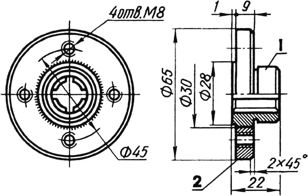
1 — turned standard sprocket; 2 — flange
“Firefly” is a design that can be said to be time-tested, so I recommend it to practical craftsmen. To those who are more inclined to experiment, I would like to suggest possible ways to modernize it.
First, instead of the automotive generator G-250 with a built-in rectifier unit and contactless-transistor relay-regulator RR-350, models of later releases can be used, for example G-21 and RR-24. Or generator G-130 with self-excitation together with RR-130, etc.
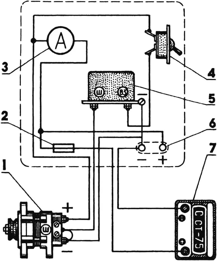
1 — generator G-250; 2 — 15 A fuse; 3 — 20 A ammeter; 4 — switch V-45; 5 — relay-regulator RR-350; 6 — socket for connecting DC consumers at 12—14 V; 7 — battery
Second, abandon the remote control panel by mounting all necessary electrical devices on a U-shaped bracket made of sheet steel, fixed on the frame gusset, or generally make the panel on the gusset.
Third, use a shorter V-belt and thereby reduce the dimensions, and consequently, the mass of the structure.
“Modelist-Konstruktor” No. 1’2001, V. PETROV
Recommend to read
 WALL SOUVENIR
"Modelist-Konstruktor" awakened in me a thirst for innovation, the desire to do something with their hands. One of his simplest works, I would like to submit to the judgment of the...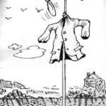 AND VANE, AND A SCARECROW
It is known that the established garden weathervane with propeller with its constant sound and vibration that is transmitted through the pole into the ground, drives away from the area...
