
To convert the motorcycle to a batteryless setup I purchased: an AC generator 43.3701 (from Minsk or Voskhod motorcycles), two thyristor ignition modules KET-1, a BKS-261.3764 unit, an inductive pickup, plus 12 V lamps and a horn. You can also make a 12 V generator from two G427 units taken off older motorcycles: use one as the base together with its lighting section (wound with thick wire) and take only the lighting section from the second one. Remove three thin-wire sections from the first generator (leave the ignition winding under the metal shield) and install the borrowed lighting winding in their place. Connect the two sections in series. If, after testing on the motorcycle, the output voltage drops instead of increasing, swap the leads of one section.
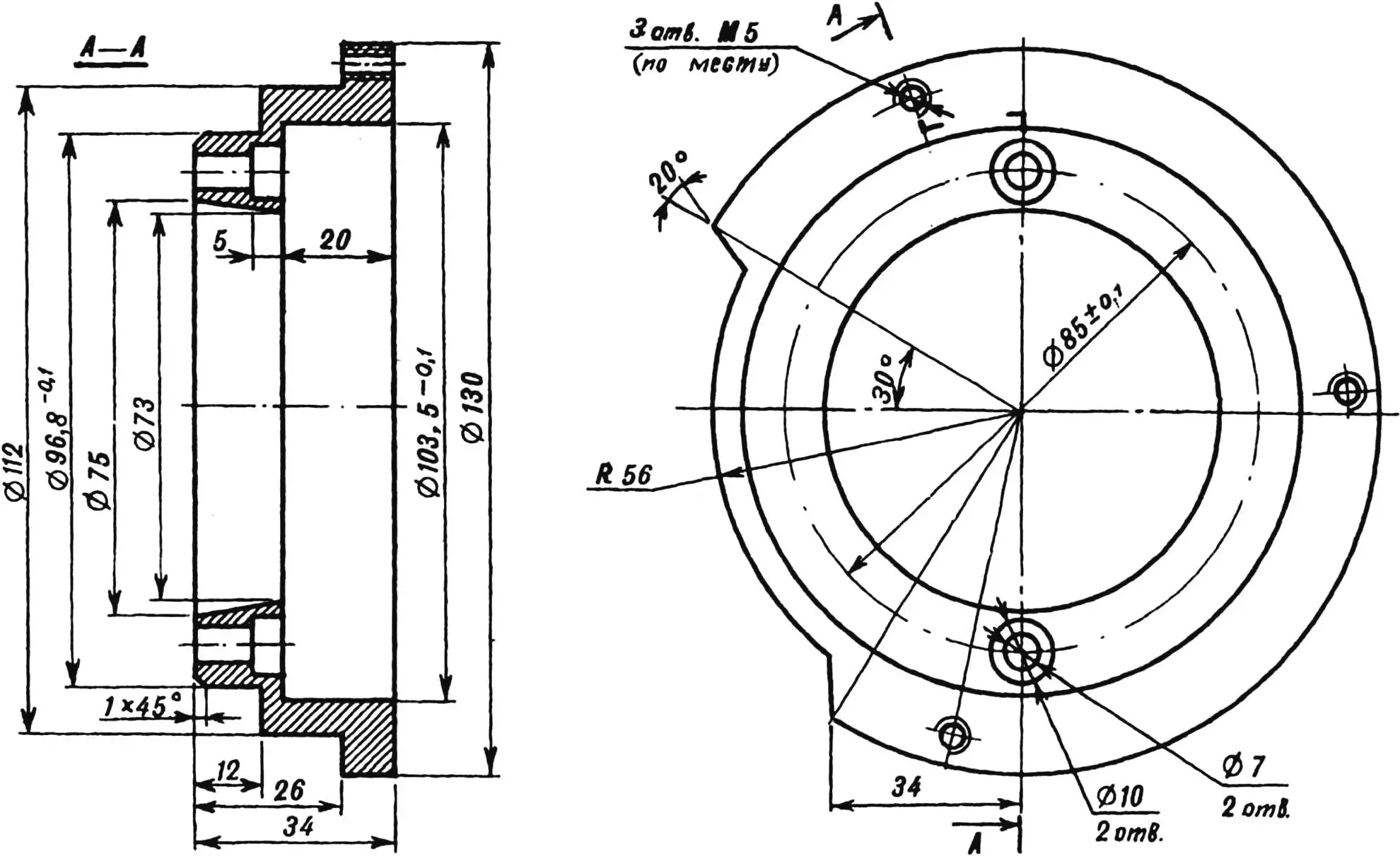
Machine an adapter flange from steel of any grade, press it into the crankcase bore, and fasten it with M6×30 screws. When marking the holes on the flange, use the generator stator as a template. To fit the rotor onto the crankshaft stub, drill and file a new keyway for the locating pin. Do not cut the keyway elsewhere—otherwise the generator will sit incorrectly in the crankcase. Because the new generator is compact, the right crankcase cover almost needs no rework: remove a portion of the partition as shown and glue in an extra 5–6 mm aluminum baffle (size to fit). Glue a similar partition inside the crankcase to seal the generator compartment. The best adhesive is epoxy filled with fine aluminum chips.
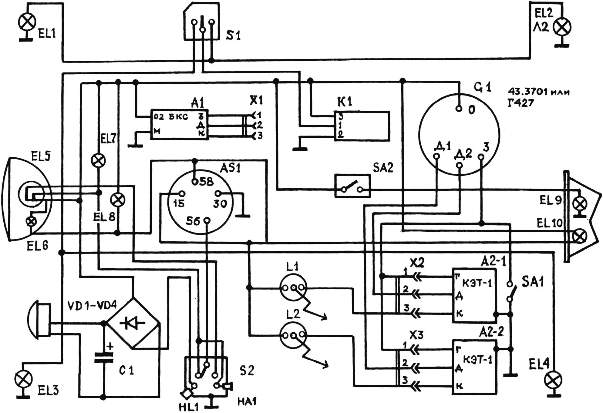
EL1–EL4 — turn indicators (12 V, 15 W); EL5 — high/low beam (12 V, 40/35 W); EL6, EL10 — position lamps (12 V, 4 W); EL7 — high-beam indicator (12 V, 2 W); EL8 — speedometer light (12 V, 2 W); EL9 — stop lamp (12 V, 20 W); SA1 — anti-theft switch; S1 — turn indicator switch; S2 — headlight/ horn switch; X1–X3 — identical connectors; VD1–VD4 — KD202 diodes; C1 — electrolytic capacitor 4…10 µF (25 V); A1 — BKS-261.3734 unit (12 V); AS1 — ignition lock; L1, L2 — ignition coils; K1 — flasher relay; SA2 — brake-light switch; A2-1, A2-2 — electronic thyristor modules (KET-1); G1 — generator 43.3701 or G427 (terminals: O — main 12 V windings; З — ignition windings; D1, D2 — pickups of cylinders 1 and 2); HL1 — pilot light; NA1 — horn.
Now to the generator itself. The most laborious task is fixing the inductive pickup for the second cylinder. Accurate positioning is essential to keep the ignition advance identical in both cylinders. Because the housing lacks a seat for that pickup, some terminals must be relocated. For layout, mount the generator on the engine. Using a dial indicator, find top dead center (TDC) of one piston, orient the generator so that the rotor magnet slot aligns with the pickup core lug, and tighten the mounting screws. Then check the other crank throw, find its TDC, press the pickup against the housing, and mark its spot. Existing terminal holes will appear at the intended mounting points, so rivet two small 3‑mm-thick steel tabs inside the housing, drill them, and tap M4 threads for the pickup screws. Take care not to damage the ignition winding while drilling.

Since it is almost impossible to hit the exact pickup position on the first try, fasten each tab with a single rivet. With this setup you can loosen the screws and shift the pickup slightly during final adjustment. The prepared generator can now be installed. To see at what rotor position the spark fires—important for dialing in the advance—use a stroboscope. At sub-medium rpm and with the rotor-to-pickup gap set to 0.3…0.6 mm, the distance “a” equals 1 mm; as rpm rises it increases by roughly 0.6 mm, providing automatic advance.
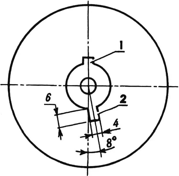
1 — keyway; 2 — dowel recess.
Remove the stock regulator relay and install two KET-1 modules in its place, ensuring their cases make solid contact with the motorcycle ground. The BKS block, which houses the voltage stabilizer, is clamped under the tank between the ignition coils and the air filter. Cover the compound-filled face of the BKS block with a flat duralumin plate.
Because the new generator keeps the ignition and lighting windings separate, the wiring harness needs major revision. In the updated schematic every load stays connected to the generator permanently; the wire switched by the ignition lock ties chassis ground to terminal 30. Thus the rider sees no difference: pushing the key in turns on the ignition, turning it to “1” switches on the sidelights, and “2” powers the headlamp. For the same reason the tail lamp must be modified—remove it and rework the running-light socket so both leads are insulated from the housing, as on the schematic.
Both ignition modules are fed from a single coil; its output is ample for normal operation. Toggle switch SA1 under the seat blocks engine start. The modules connect to the harness via plugs X2 and X3, while the identical X1 connector goes to the BKS unit (A1). Should one KET-1 fail, simply unplug its connector and insert it into the BKS unit to keep riding. The BKS block’s primary job is stabilizing onboard voltage: the generator’s “0” winding, which powers every load except the ignition system, ties into terminal 02 of the BKS. The ignition coils L1 and L2 remain stock.
When replacing the headlamp bulb, swap the narrow spade terminals for wide ones or file the bulb contacts so their width matches the socket.
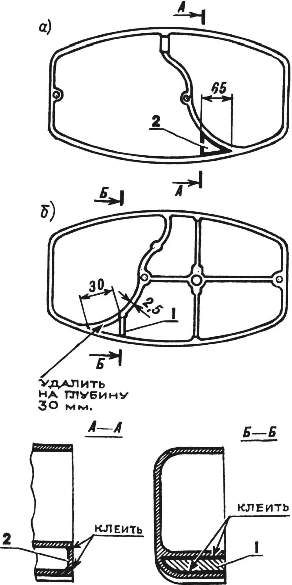
1 — baffle; 2 — plate.
After fitting the new generator you may face issues hooking up the horn. To use an automotive horn that runs only on DC, assemble a rectifier with diodes VD1–VD4 and capacitor C1.
Capacitor C1 should be large—4…10 µF rated at no less than 25 V. If you cannot find a single capacitor of the right value, build one from several wired in parallel. Mount the rectifier on a triangular insulating plate (e.g., textolite) bolted beneath the fuel tank inside the triangular frame space. If the capacitor bank will not fit there, relocate it to any other convenient spot.
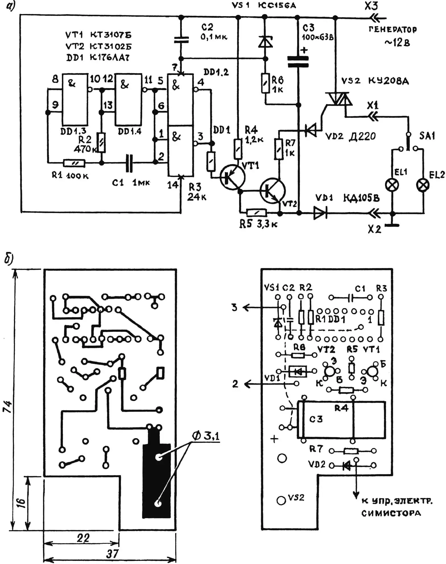
You can use a stock 12 V flasher relay K1 from a Voskhod or Minsk motorcycle, or build an electronic one. The latter keeps a steady flash rate even when the onboard voltage dips at idle.
IC DD1 forms a pulse generator with its frequency set by resistor R2. Through the current amplifier on transistors VT1 and VT2, the pulses drive the gate of triac VS2. Diode VD1 rectifies AC; VS1, R6, and C2 make a parametric stabilizer that powers IC DD1; SA1 is the turn-indicator switch; EL1 and EL2 are the indicator lamps.
Relay K1 sits inside the housing of a polarized RP4 relay. The triac VS2 is mounted on an aluminum angle secured to the board with two rivets. A circuit assembled from good components needs no additional tuning.
Modelist-Konstruktor No. 2’2000, S. Savinovsky
Recommend to read
 AUTOROLLER — DWUHLOPASTNY CAR
Probably not be an exaggeration to assume that at least half of the permanent readers of the "Modeller-designer" wants to make their own car. In the following constructions as the power... THE TRUCK PAPER
The entire model except for the axles and the engine is made of paper and cardboard. It can make students 3rd-5th grade. The model is like a real machine of the separately mounted parts,...
