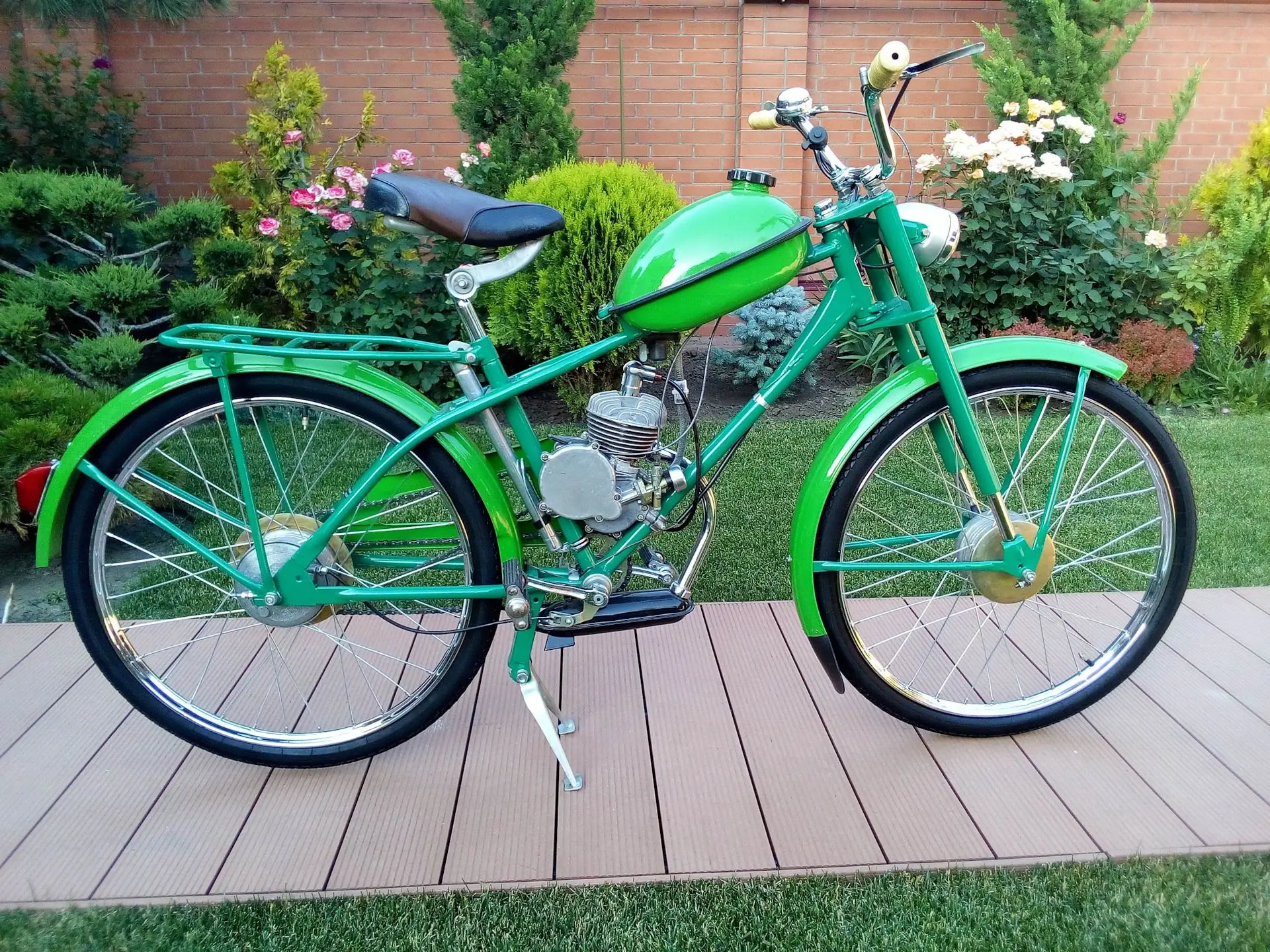
The owner of a light moped (or, according to modern classification — a mo-vel, that is, a motorized bicycle), equipped with a D-8 engine, eventually notices that their two-wheeled machine doesn’t start easily enough, sometimes can’t pull uphill or poorly overcomes off-road conditions. And starting the engine with bicycle pedals, on the go, is not very convenient. However, such a moped can be improved.
To begin with — footrests. Young “rockers” remove the bicycle drive chain in the first month of operation, leaving the pedals only as a footrest and for braking. True, this support is quite shaky, and to brake with pedals, you need to turn them almost half a turn backward. A solution to the situation can be equipping the moped with motorcycle-type footrests and a real brake pedal.
To do this, remove the entire bottom bracket assembly together with the drive sprocket, bottom bracket axle, brake lever ratchet, the lever itself, and pedals. Instead, install a homemade assembly in the same frame opening, consisting of footrests (from any moped or light motorcycle), welded to bases — tube sections with an outer diameter of 20 mm. Weld a nut with M8 thread (on the left) and a bushing with an 8.5 mm diameter hole (on the right) into the free ends of the tubes. On the right 20 mm diameter tube, put on a bushing (a tube section with an inner diameter of 20 mm) with a brake pedal welded to it, bent from a 10 mm diameter rod.
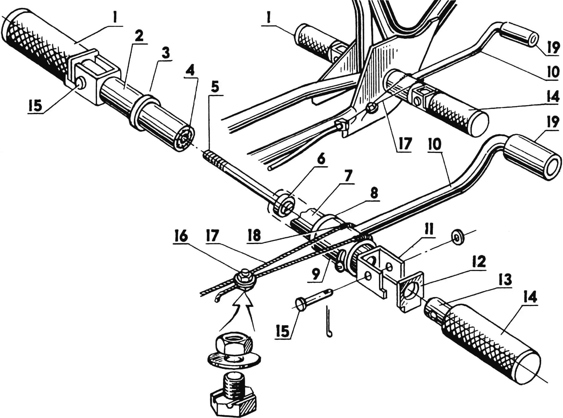
1, 11, 12, 13, 14, 15 — footrest parts from a heavy moped or light motorcycle; 2, 7 — footrest bases (steel tube 20×1.5); 3, 8 — thrust rings; 4 — M8 nut; 5 — M8 bolt; 6 — bushing; 9 — brake pedal bushing; 10 — brake pedal (steel rod Ø 10); 16 — clamp (modified M8 bolt with nut and washer); 17 — cable; 18 — cable braid section; 19 — tube (rubber).
Mounting the assembly on the moped is not difficult. Insert the footrest bases into the bottom bracket opening and connect them with an M8 threaded bolt. You’ll have to tighten this bolt with a screwdriver, so pre-cut a slot 2-3 mm deep in the bolt head. To prevent the pedals from coming loose, place an elastic split washer under the bolt head.
Some difficulties may arise when connecting the brake pedal to the rear wheel brake mechanism. The fact is that the standard cable is too short for this, and it should be replaced with another, longer one. Its attachment to the brake pedal is simple and, as practice has shown, very reliable: the cable loops around the brake pedal and is clamped with a short M8 threaded bolt, washer, and nut. File two grooves on the clamp bolt head with a round file — they will prevent the cable from slipping out of the clamp. To prevent the cable from chafing at the contact point with the pedal, put a section of cable sheath from a throttle or brake control cable on it. To return the pedal to its original position, equip it with a return spring.
Gearbox for the moped. Your engine will easily handle road difficulties if you equip it with the simplest gearbox. As can be seen from the figure, the gearbox is designed like a sports bicycle gear shifting mechanism. But for a moped, only two sprockets are needed — two gears are quite enough for it.
We don’t claim that making and adjusting such a gearbox is a simple matter. On the contrary, it requires certain metalworking skills, lathe work, and welding.
Now — about the gearbox itself. One sprocket on the moped already exists — the standard driven one, the one fixed on the rear wheel. Another one with a larger number of teeth is needed — approximately 10 more than on the moped. Such can be bought in a store that sells spare parts for bicycles and mopeds. Note that sprockets from some children’s bicycles are also suitable.
If you can’t find a ready-made sprocket, then make it yourself, first calculating its radius. To do this, multiply the chain pitch value (the moped’s motor chain pitch is 12.7 mm) by the number of teeth of the future sprocket — you’ll get the pitch circle length. Dividing it by 2π=6.2832, you’ll get the radius.
Select a duralumin blank from s4 sheet and draw a circle of the calculated radius on it, then carefully divide it into a number of parts equal to the number of teeth using a marking compass. Mark the hole centers with a center punch and drill them with a drill of the same diameter as the chain roller. Cut the blank along the circle of tooth protrusions and file their tips.
Mount the sprockets on the rear wheel so that the larger one is at the wheel hub.
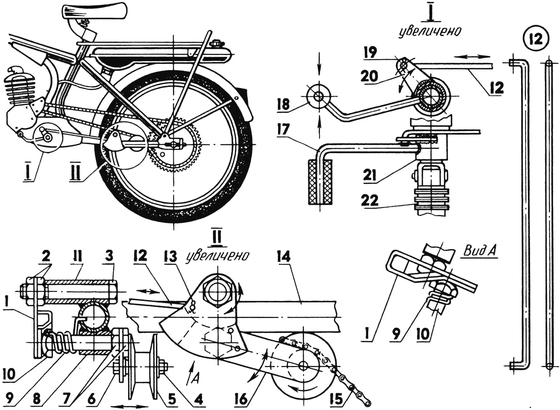
1 — cam sector; 2, 4, 7 — nuts; 3, 6 — bolts; 5 — support pulley; 8 — lower bushing; 9 — spring; 10 — support axle; 11 — upper bushing; 12 — drive rod; 13, 19 — cotter pins; 14 — moped frame; 15 — bushing-roller chain; 16 — support lever; 17 — pedal; 18 — rubber bushing; 20 — lever; 21 — pedal bushing; 22 — footrest.
Next — the gear shifting mechanism. How it’s arranged is clear from the figure. Two bushings are welded to the left lower fork blade of the moped’s rear wheel. A support — a spring-loaded lever with a small pulley at its end — is fixed in the lower one. The lever can move in the bushing left and right, throwing the chain from one sprocket to another, and the spring constantly keeps the chain in a tensioned state. A cam sector is installed in the upper bushing: when moving, it pushes the support away and thereby throws the chain from the small sprocket to the large one. When the sector moves in the opposite direction, the spring pushes the support back to its original position, and the chain transitions to the small sprocket.
And finally, the gear shift pedal. It consists of a bushing with a pedal platform and lever welded to it. The lever is connected to the cam sector with a rod made of thick wire. Thus, when pressing the pedal, the chain is thrown onto the large sprocket — first gear is engaged. If you hook the pedal with the toe of your boot and push it up, the chain will jump to the standard sprocket and second gear will engage.
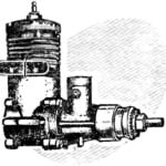
Kickstarter for the moped. Do you know what the difference is between a moped and a moped with kickstarter? A moped is mo-tor plus ped-als, and a moped with kickstarter is mo-tor plus kick-starter. Of course, starting the engine with a starting device is easier and more convenient than with pedals.
To begin with, let’s understand the kickstarter device. If you remove the right cover from the D-8 engine crankcase, you’ll find a large gear wheel underneath, engaged with the small crankshaft gear. This wheel will become the basis of the starting device. Cut inclined teeth on its end face, thus turning it into a kind of ratchet. The depth of each tooth is 2-2.5 mm, the pitch — every two or three wheel teeth. By the way, focusing on them, you can quite accurately maintain the distances between the ratchet teeth.
Modify the crankcase cover as well. Cut a slot about 5 mm wide in it (its shape is shown in the figure) and fasten an axle-bracket with screws for installing the starting device lever.
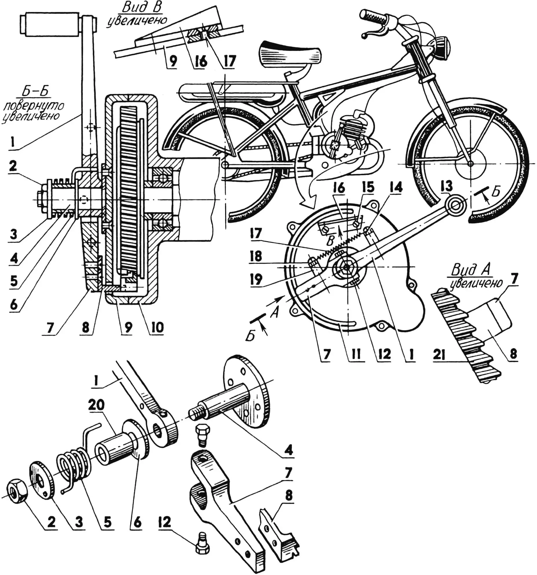
1 — starting device lever; 2, 14 — nuts; 3, 6 — washers; 4 — starting lever axle-bracket; 5 — starting lever return spring; 7 — fork-lead; 8 — two-tooth ratchet pawl; 9 — crankcase cover; 10 — engine crankcase; 11 — ratchet pawl slot; 12 — fork-lead fastening screw; 13 — starting device lever pedal; 15, 18 — screws; 16 — deflector; 17 — fork-lead fixation spring; 19, 20 — bushings; 21 — engine gear wheel.
It’s better to use a ready-made lever for the starting device — from the moped’s bicycle drive or any bicycle. Its modification comes down to cutting the pedal axle to 70 mm, after which stretch a section of rubber hose onto the axle.
Connect the fork-lead to the starting device lever with a hinge (with two screws). Cut it from duralumin and rivet a two-tooth ratchet pawl to the free end so that the teeth cut in it match the ratchet teeth.
Two springs are used in the starting device mechanism. One, located on the kickstarter lever axle and working on torsion, serves to return it. The second, connecting the lever and fork-lead, works on tension and is designed to fix the lead in two positions: pressed against the ratchet wheel and pushed away from it.
And one more important detail — the deflector, which throws the lead away from the ratchet wheel at the end of the working stroke. Without it, starting can turn into an engine accident — the lead will cut into the crankcase cover. To prevent this, fasten a duralumin angle with a beveled shelf on the crankcase cover. Hitting it at the end of the working stroke, the lead lifts up and disengages from the ratchet.
Try starting the engine now. Disengage the clutch by putting the lever on the latch, move the lead to the position where the pawl engages with the ratchet wheel with the toe of your foot, and boldly press the pedal.
«Modelist-Konstruktor» No. 8’98, I. ZHUKOV
Recommend to read
 “COMET” WILL BE MORE POWERFUL
Engine MD-5 Kometa is produced in large series for many years and is established on the models of different types. To simplify manufacturing and reduce the cost of manufacturing allows...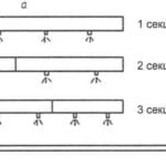 THE GARDEN WATERING GUN
The device of "Automatic" is intended for irrigation of vegetable and fruit plants to individual garden plots. Watering is carried out automatically at specified intervals (e.g., daily)....
