It was named a hydrocart, although it looks more like a kind of water motorcycle. This sports micro-vessel was built at the Donetsk Regional Young Technicians’ Station in the “Small Shipbuilding” club. As the station director N. V. Vasiliev reported to the editorial office, the club is celebrating its fifteenth anniversary this year. At first, during the sessions, young technicians studied the design and purpose of various sports and pleasure boats, developed new designs, mainly motorboats. The work greatly interested the youngsters, but it still felt like something was missing. Soon it became clear that the young “shipbuilders” wanted not only to create motor vessels, but also to test them themselves and, moreover, to compete: whose machine would turn out to be faster and therefore technically more advanced.
For these purposes, they needed a micro-vessel that would be simple to build, original in layout, and safe under way, able to satisfy boys’ thirst for racing on the water. They wanted to find an option best suited to the capabilities and age of young boatbuilders. This design turned out to be the hydrocart.
The first prototypes were created ten years ago. They immediately showed that the direction of the search had been chosen successfully. The micro-vessel unexpectedly combined attractive qualities of a motorcycle, a scooter, and water skis: the racer sat astride and steered like a motorcyclist, while the hull of the craft resembled a scooter, and in turns it almost went up on edge like a water ski. From one prototype to the next, the overall layout, the remote control system of the outboard motor, and the hull bottom shape — which largely determined the running performance of the craft — were improved.
In 1973, the first competitions were held, with 10 teams from four cities of the Donetsk region already taking part. Thus, a new type of powerboating appeared in the region — hydrocarting. The birth of this sport was supported by our magazine, which published a description and drawings of the hydrocart, course layouts for competitions, and sample rules developed at the Donetsk Regional Young Technicians’ Station. These materials caused a great response: many letters came to the station from clubs and individual enthusiasts of technical creativity.
“Hydrocarting as a sport,” writes N. V. Vasiliev, “has taken quite a firm place in the life of many children’s technical creativity groups in our region. Last year we already held the eighth regional competition among schoolchildren.”
Today, 16 clubs of young hydrocarting enthusiasts operate at city and district young technicians’ stations. This means that the technical search for the best design of this unusual sports micro-vessel continues. More than 10 types of hydrocart were developed between 1972 and 1980. By offering one of them to our readers, we hope that this publication will further popularize hydrocarting—an interesting field of technical creativity and exciting water competitions, as well as an elementary training stage for helmsmen and deckhands of small craft fleets.
1 — hull, 2 — seat box, 3 — seat cushion, 4 — fuel tank, 5 — knee brace (knees), 6 — roller, 7 — steering bracket, 8 — engine, 9 — throttle cable bracket, 10 — transom, 11 — steering cable, 12 — throttle grip, 13 — emergency cut-off switch, 14 — handlebar, 15 — steering shaft, 16 — decorative ring, 17 — drum, 18 — shaft thrust block, 19 — handle.
“Mustang” is a sports motorboat with a “deep V” hull and a flat bottom section. The design is based on the hydro-ski principle used in the widely known “Sea Sled” boat by W. Fox. Such a craft easily climbs onto the wave and at the same time does not jump out of the water even at very high speeds, because the long and narrow ski is insensitive to changes in angle of attack, absorbs loads relatively gently, and the impact force on the wave is relatively small.
The “Mustang” hydrocart reaches speeds of up to 50 km/h. It is easy to handle, has small overall dimensions and weight (about 40 kg), and can be used not only for sport but also for enjoyable recreation on the water.
HULL CONSTRUCTION
Construction of the hydrocart should start with the frames. Their dimensions are taken from the table of lofting ordinates and transferred to graph paper; each frame is drawn full size. Then the drawing is transferred to cardboard or heavy paper—this gives us templates.
Using these templates, three frames of the hydrocart are marked out. The first is cut from 4 mm plywood; its perimeter frame is made from 20×30 mm battens fastened with screws and epoxy resin. The second and third frames are solid, made of pine boards 15 and 20 mm thick, respectively.
On the finished frames, slots are marked out and cut for the subsequent installation of stringers and the keel. They are spaced every 150 mm from the centerline plane. All longitudinal stiffeners and side planking are made of straight-grained pine. There are six deck stringers with a cross-section of 15×15 mm. The same dimensions are used for the bottom stringers, which must run under the longitudinal steps (redans) attached to the finished hull. For the side planking, a 15×50 mm pine strip is used, and for the keel—a 20×40 mm section.
The transom board does not necessarily have to be solid. It can be built up from 30×40 mm pine bars and sheathed on both sides with 4 mm plywood, using screws and epoxy resin. The dimensions of the transom plate are 38×290×380 mm.
To assemble the hull framework, you will need a building jig made from boards with a 30×200 mm cross-section. It is a rectangular frame measuring 400×2000 mm, which is best set up on a table or trestles for convenient work. Using a spirit level, the deck line is marked on the jig: it must not be more than 150 mm above its lower edge. Along this line, the spacing is laid out and slots are cut for the frames. Next, the centerline is marked and a steel wire is stretched along it; this is used to align the centerline marks on all frames (taking into account that the hydrocart is assembled upside down, keel up).
The first frame is attached to the end of the jig. The second frame is set just as strictly perpendicular to the deck line, and the transom is set at an angle of 10° to it.
Bottom stringers, the keel, and the side planking are then fastened to the frames with screws and epoxy resin.
After a day, the framework is removed from the jig, and further assembly of the hydrocart is carried out upside down on a flat table in a specific sequence. First, the deck stringers are installed with screws and epoxy resin; their length is limited by the first frame. To give the bow section of the hydrocart the desired curvature, a template is made from 4 mm plywood. Two 20×20 mm strips are nailed “with clinched nails” and glued with resin to its upper edge; they will serve to fasten the plywood sheathing. To bend the strips to the template shape, cuts are made to one-third of their thickness. On the side facing the first frame, the strips are extended slightly so that they can be fixed to the frame; for this, a slot is marked and cut in the frame in the centerline area. The lower edge of the template is let into the keel and fastened with screws in resin.
The free ends of the bottom stringers and side planking are secured with a 20×50×400 mm pine block. In turn, it is symmetrically let into the template and fastened with screws in resin to the keel and the template strips. The 50 mm-wide face of the block must be at deck level.
The transom plate is attached using four M8 bolts and epoxy resin. To increase the stiffness of the transom, a knee brace must be made—a triangle from a 40 mm-thick pine block with sides AB = 300 mm, BC = 200 mm, AC = 400 mm. It is sheathed on both sides with 4 mm plywood using screws and resin. Side BC of the knee is fastened to the keel with a bolt and resin, and side AB—to the plate.
Once the “skeleton” of the hull has been prepared, you can proceed to sheathing it. For this, 4 mm plywood is used. Work should begin with the bottom. Along the perimeter of each plank, a strip of fiberglass in resin is laid to ensure watertightness; the plank itself is fastened with screws and clinched nails, also in resin.
The bottom is sheathed in the following order. First the inclined sections, then the flat one; the sheet for the flat section must be 80 mm wider than the section itself. If the required plywood size is not available, separate pieces are joined along the edges “on a scarf” using resin and are riveted with copper nails.
Before proceeding to the deck and bow sheathing, all joints inside must be coated with resin and then reinforced with strips of fiberglass. After drying, the entire internal surface is coated with waterproof varnish. For ease of carrying, three handles are attached with M6 bolts: two to the transom and one to the template strips.
Deck sheathing is done with 4 mm plywood using the same technology as for the bottom. The inner face of each sheet is first coated with waterproof varnish, except in the areas where it bears on the framework. A slot is cut for the knee brace, which, after the plywood is fixed, is wrapped with fiberglass.
The bow section is sheathed with two sheets of 4 mm plywood. Each piece is fastened along the edges to the template strips, the first frame, the hull side, and the block let into the template. The technology is the same as for the bottom and the deck.
| Lines of the theoretical drawing | Frames | Transom Tr | |
|---|---|---|---|
| 1 | 2 | ||
| Half-breadths from CL | |||
| Break line (Bl) | 150 | 150 | 150 |
| Chine line (Ch) | 450 | 516 | 550 |
| Side line (Sl) | 450 | 516 | 550 |
| Heights from BL | |||
| Break line (Bl) | 55 | 0 | 0 |
| Chine line (Ch) | 147 | 137 | 137 |
| Side line (Sl) | 187 | 187 | 187 |
| Distance of steps (redans) from CL (measured along the bottom planking) (L) | |||
| 1st step line (P₁) | 175 | 191 | 202 |
| 2nd step line (P₂) | 334 | 377 | 394 |
| 3rd step line (P₃) | 473 | 549 | 581 |
When the entire hull is ready, you can proceed to making the seat box. The sides are made of 4 mm plywood, and the 150×290 mm frame is made of 20×40 mm pine bars; it is fastened to the first frame with screws and resin. Slots are cut in the frame and in the transom plate so that two 20×20 mm strips can be laid in them, with their upper face 150 mm above deck level. The distance between the outer faces of these strips must match the width of the transom plate.
Directly under these strips, the same kind of strips are fastened to the deck—this forms the seat box, to which the plywood sides are screwed. At the point where the seat box height changes from 150 to 230 mm, a pine crosspiece is installed. Another crosspiece, made from 10×200×290 mm plywood, will serve both as a stiffener and as a support for the steering shaft.
After all assembly work is completed, the hull must be sanded with sandpaper and all seams taped with strips of fiberglass on epoxy resin. Then the entire bottom, deck, bow, and seat box are sheathed with fiberglass mesh or gauze in resin. The cloth is laid carefully and rolled out thoroughly to avoid air bubbles; edges overlap by 20–30 mm. After drying, the entire glassed surface is smoothed with an abrasive stone.
It remains to make the seat cushion and to install the steps (redans) on the bottom. A frame is prepared for the cushion, its dimensions dictated by the internal perimeter of the seat box. A 10 mm plywood panel is fastened to the frame with screws in resin; together they form a lid for the box. The top is upholstered with artificial leather over a foam pad, forming a soft seat cushion.
The steps (redans) are cut from a 10×40 mm bar and have a triangular section, with the wide face parallel to the bottom. The first step is set under the projecting edge of the flat bottom sheathing; the second—along a stringer, and the third—along the side planking. All of them are installed with a strip of fiberglass underneath and fastened with screws in resin.
REMOTE CONTROL
Construction of the hydrocart ends with the installation of remote control for the outboard motor. It includes a motorcycle handlebar, a steering drum, steering and throttle cables, a throttle grip, a steering bracket, and two rollers. A shaft of arbitrary length made of 20 mm steel tube is welded to the motorcycle handlebar. A drum made of duralumin or textolite with a diameter of 200 mm and a height calculated for 2–3 turns of 3–4 mm cable is mounted on it.
A bronze thrust block is mounted at the end of the shaft, and the hole in the seat crosspiece is reinforced with a bronze ring, which also serves a decorative function.
The steering bracket is a clamp with two “wings” welded to it, all made from a 40 mm-wide, 4 mm-thick steel strip. The total length of the wings must not exceed the drum diameter. The clamp is fastened to the engine housing with an M10 bolt at such a height that it prevents misalignment of the steering cable, which is attached to the wings via turnbuckles and runs through 40 mm rollers mounted in L-shaped brackets at the edges of the transom plate.
To secure the throttle cable on the engine, a U-shaped bracket made from 3 mm-thick steel strip must be installed. A slot is cut in the engine cowl for the cable to exit. To ensure automatic throttle return, a spring is installed on the throttle lever. In addition, the hydrocart must be equipped with an emergency stop switch that shuts off the engine if the driver falls from the seat.
PAINTING
The very last operations are the finishing ones. They are performed in the following order. The hull and all parts to be painted are degreased with acetone or baking soda solution. Irregularities, gaps, and scratches are filled with epoxy resin or PF-00-2 primer. After drying and sanding, a general puttying is done with the same materials. Then again drying and sanding, followed by overall priming with zinc white, another drying, and local touch-up priming. The prepared surface is painted with decorative enamels: pentaphthalic No. 570, PF-115, or glyptal enamels. Then come drying, polishing, and final coating with waterproof (pentaphthalic or glyptal) varnishes, followed by final drying and polishing.
I. TSYGANKOV, head of the hydrocarting club at the Donetsk Regional Young Technicians’ Station
Recommend to read
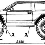 ROVER… HIGH COMFORT
For residents of the Urals, Siberia, North, Far East (that is, the most part of the country) the need for such a car, as the Rover is simply a vital necessity. The reasons are many: good...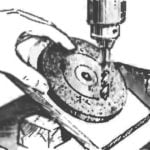 THE DRILL WILL SHARPEN
There are special devices for sharpening dull or broken drill bits If they are not at hand then try under a rotating drill bit set suitable abrasive (e.g. abrasive wheel) at an angle of...
