
The age of the members of the “Planeta” young technicians station varies greatly: from elementary school students to graduates. And if high school students are more interested in serious equipment (motor blocks, snowmobiles, all-terrain vehicles, etc.), then for younger ones, light motorcycles are most attractive, so they can start it themselves and ride with the wind. Therefore, the technical creativity of each new generation of young inventors usually begins with the development of a mini-moped. One such machine was described in the publication “Gasoline Not Needed” in No. 9 of 1997 of “Modelist-Konstruktor”. It discussed a design based on the frame and chassis of a Riga mini-moped with a drive from an MN-1 series-wound electric motor. Unfortunately, this idea has not yet been developed, as it was not possible to find a lighter but capacious battery instead of the heavy automotive one that had to be used in this design. Therefore, in the future, traditional gasoline engines of the D-6, D-8 type were used to drive mopeds.
This article will discuss such a development.
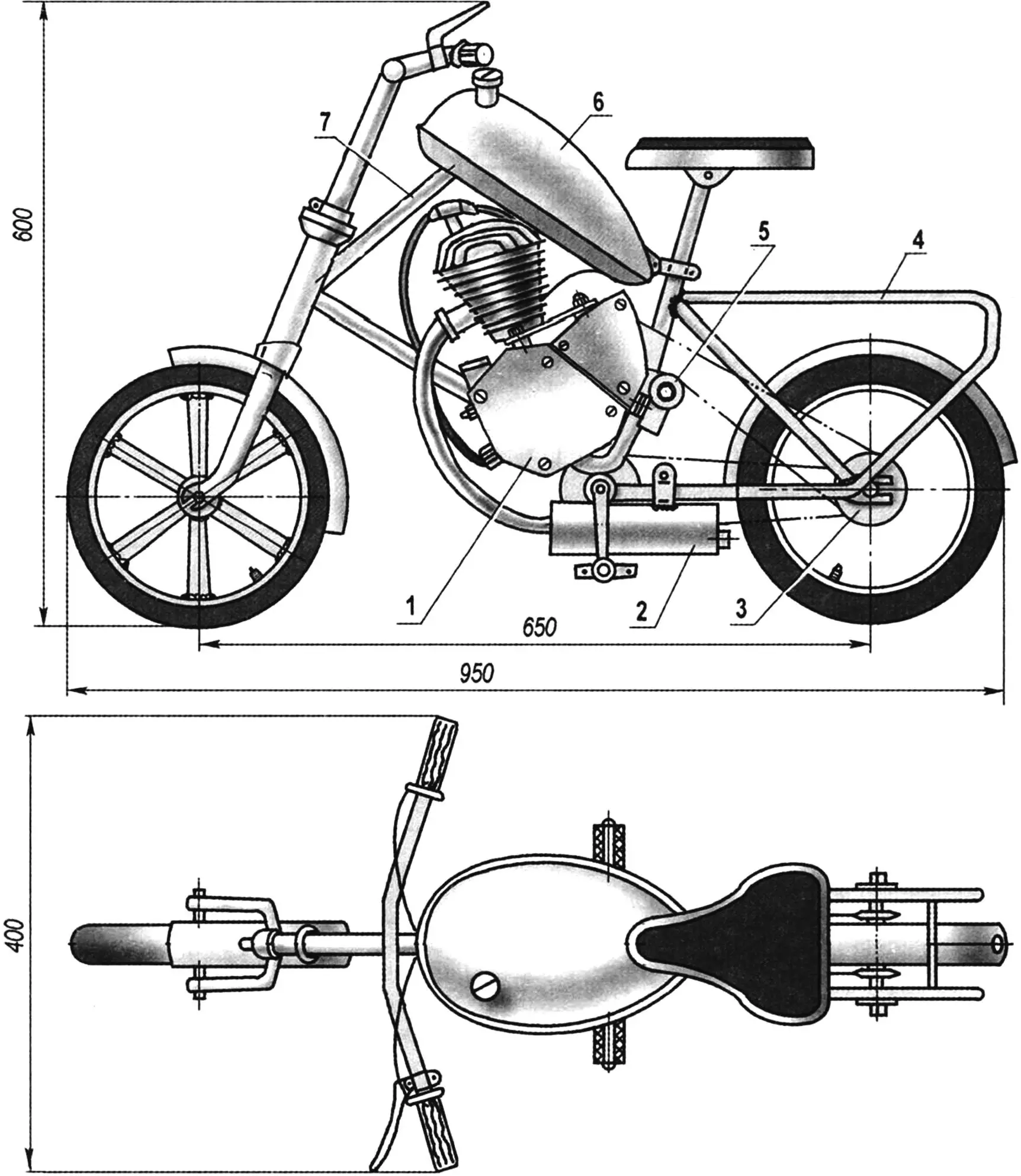
1 — D-8 engine; 2 — muffler; 3 — driven sprocket of the motor drive; 4 — brace (tube Ø12, 2 pcs.); 5 — tension roller; 6 — fuel tank; 7 — subframe (tube Ø27)
An ordinary children’s bicycle was taken as the basis for the mini-moped (fig. 1). Taking into account the difficult operating conditions (speed — up to 60 km/h), the frame and wheels of the future moped were reinforced. A subframe made of a 27 mm diameter tube was welded between the seat tube and the steering tube. In addition to reinforcement, the subframe serves as a base for mounting a 2.5-liter fuel tank. The rear part of the frame is strengthened with two braces made of a 12 mm diameter tube. On the front wheel, instead of 12 standard spokes, 6 steel strips with a cross-section of 4×20 mm were welded, 3 on each side (as spokes). And on the rear wheel, the number of spokes was increased to 32, as on an adult bicycle.
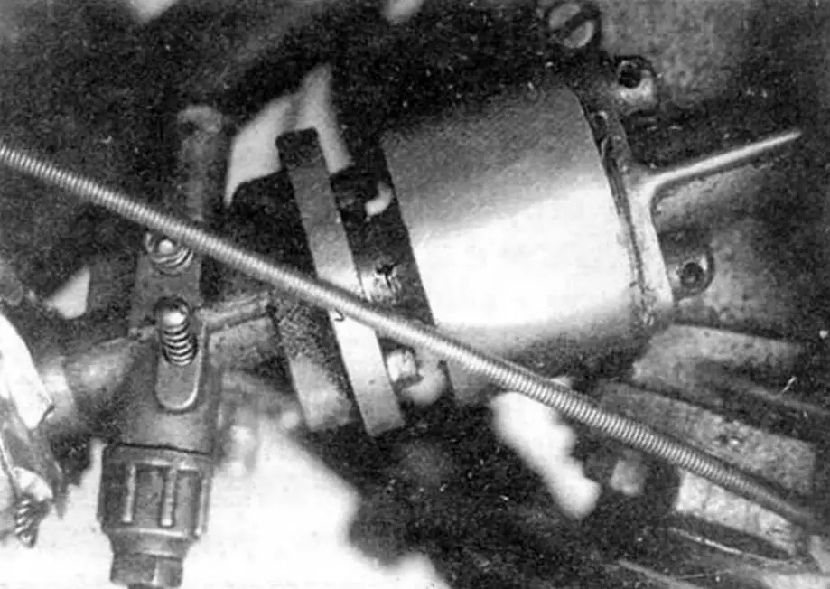
A D-8 engine is installed on the mini-moped. To increase power on the intake (between the engine and carburetor), an additional valve was placed (photo 1), and the combustion chamber height was reduced by 2.5 mm. As a result, 3 hp was obtained.
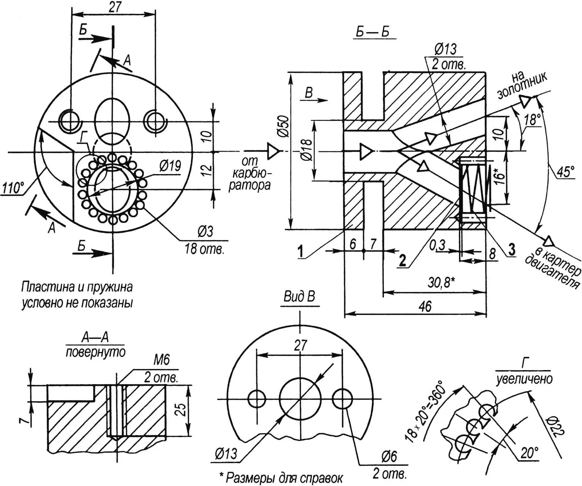
1 — valve body (D16T); 2 — plate (D16T foil, s0.3); 3 — spring (65G wire, Ø0.2)
The valve body (fig. 2) is a cylinder with a diameter of 50 mm and a length of 46 mm, made of D16T duralumin. Three channels with a diameter of 13 mm are drilled in the body: a central one, facing the carburetor, and two inclined ones that enter the central one. Part of the mixture from the carburetor flows directly to the motor spool through one of the channels, and the other part, through the channel on which the valve is installed, rushes into the engine crankcase when vacuum is created. The valve plate (D16T foil 0.3 mm thick) is slightly spring-loaded toward the carburetor. The spring with an outer diameter of 17 mm made of thin 0.2 mm 65G wire has 3 turns. 18 holes with a diameter of 3 mm are drilled around the perimeter of the recess under the valve. These holes facilitate the passage of the mixture after the valve opens. The additional volume of mixture that occurs during bypass creates excess pressure in the compression chamber, creating additional torque on the crankshaft mechanism when fuel burns and thereby increasing engine power.
Manufacturing of the valve body should begin with turning (turn, trim the ends, drill a central hole to a depth of 15 — 16 mm, turn a groove 7 mm wide to a diameter of 18 mm). After this, mark the centers of the inclined channels, maintaining dimensions of 10; 16 and 12 mm. Around the last center, mark and drill 18 holes with a diameter of 3 mm to a depth of 9 — 10 mm along a diameter of 22 mm.
This operation should be performed extremely carefully, maintaining inter-center distances as accurately as possible, since damage to the bridges between holes (approximately 0.8 mm) can during operation lead to the breaking off of pieces of metal, their entry into the crankshaft mechanism (CSM) and engine failure. For the same reason, after final mechanical processing of the valve body to remove the smallest chip particles, it should be blown with compressed air followed by treatment with a vacuum cleaner and magnet.
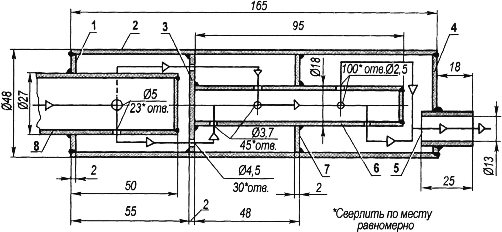
1 — inlet end (sheet s2); 2 — body (tube 48×2); 3 — perforated internal partition (sheet s2); 4 — outlet end (sheet s2); 5 — outlet pipe (tube 16×1.5); 6 —
transitional internal pipe (tube 16×1.5); 7 — blind internal partition (sheet s2); 8 — engine intake pipe
Before starting the processing of inclined channels, at the marking points of their centers, it is necessary to drill 2-mm recesses with a diameter of 10 mm. Then firmly secure the part in machine vises at an angle of 18° and in two passes with drills with a diameter of 6 and 13 mm, process the first channel (to the spool) until it exits into the central one. (It is even better to process the channels in the valve sequentially with a drill, reamer and reamer, thus ensuring not only accuracy but also high surface finish of the channels. — Ed.) Rotating the body 45°, drill the second (valve) channel. Then on a vertical milling or boring machine, process the recess for the plate and spring with a boring head with a diameter of 19 mm (to a depth of 8 mm), maintaining a dimension of 12 mm (to the center). Finally, process the mounting holes and recess (7×110°), which is necessary to accommodate the protrusion on the cylinder.
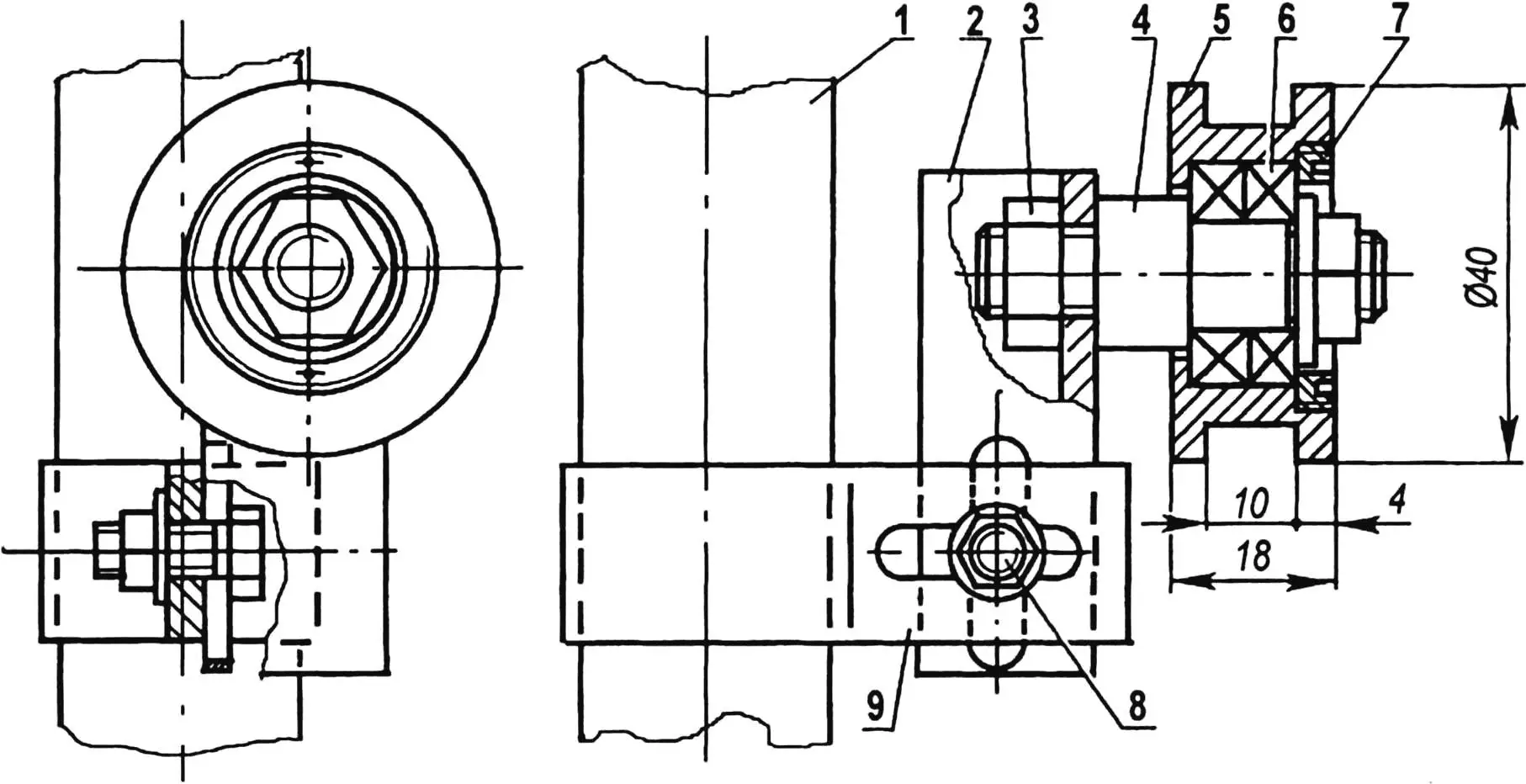
1 — seat tube Ø27; 2 — roller bracket (angle 20×20, L55); 3 — axle mounting (M10 nut, 2 pcs.); 4 — roller axle (steel, round 16); 5 — roller (steel 40Х, round 40); 6 — bearing 1 000 900 (2 pcs.); 7 — cover (steel, sheet s3); 8 — bracket mounting (M6 bolt); 9 — clamp (steel, strip 2×20)
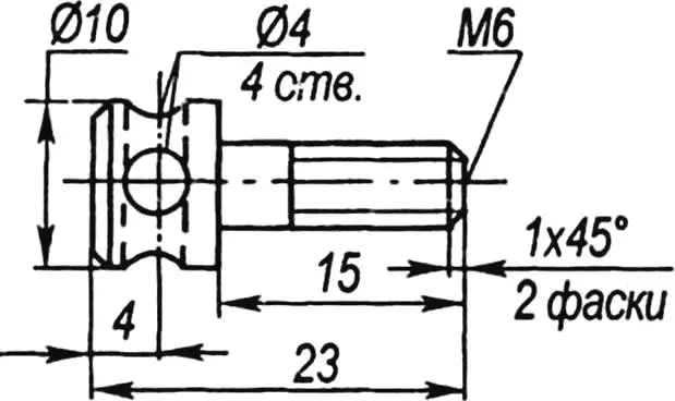
The valve mounting to the carburetor is carried out on its standard studs. But for connection with the cylinder, it was necessary to make special bolts (fig. 3, photo 1), since there was not enough space to tighten bolts with ordinary hexagonal heads with wrenches. A heat-resistant sealant is applied to seal the joint between the valve and cylinder.
The standard D-8 engine muffler was replaced with a new one (fig. 4), homemade with a body made of thin-walled tube with an outer diameter of 48 mm. The muffler has 3 compartments. Exhaust gases through 23 holes with a diameter of 5 mm at the end of the engine intake pipe, welded into the muffler inlet end, enter the first compartment. From it, through perforation (30 holes with a diameter of 4.5 mm) in the first internal partition — into the second compartment. And into the third — through the internal pipe through 45 inlet holes with a diameter of 3.7 mm and 100 outlet holes with a diameter of 2.5 mm.
And the last stage of exhaust — from the third compartment outward — through the outlet pipe. The new muffler reduced the sound level, albeit slightly, but still increased the power and maximum engine speed.
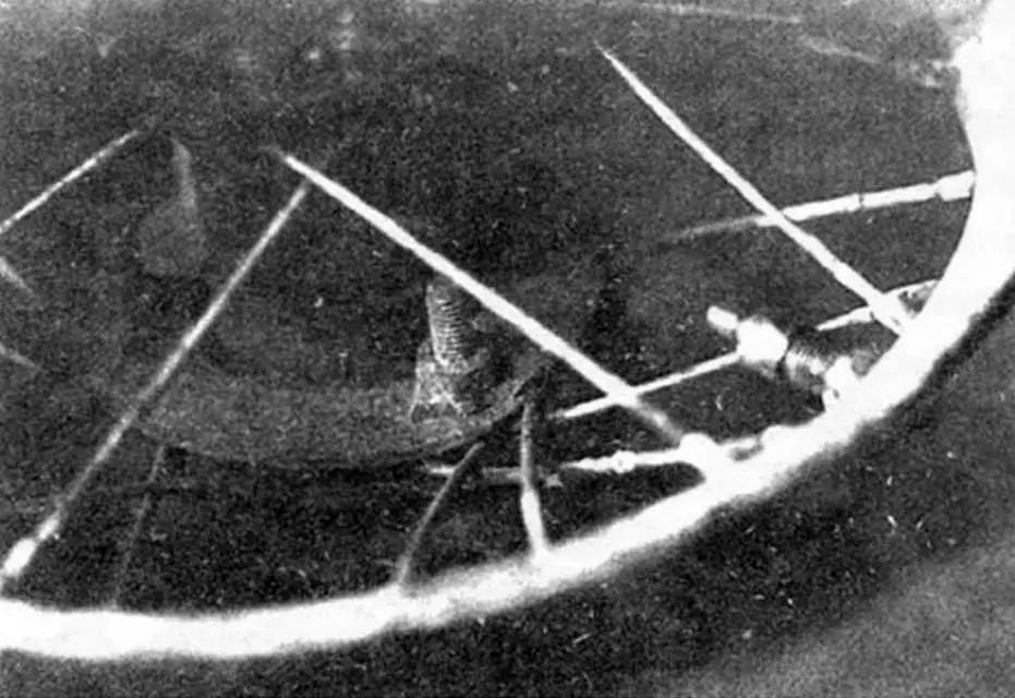
The drive to the rear wheel of the moped is carried out by a roller chain with a tension roller (fig. 5) through a homemade 24-tooth sprocket made from a 4 mm thick steel sheet of grade 40Х. Rough processing was done according to marking on a vertical milling machine with a 4-mm end mill, final — with a round file. The sprocket is attached to the rear wheel hub flange with M6 bolts. On the spoke side, special segment washers with rubber gaskets are installed, as on a motorized bicycle (photo 2).
The mini-moped is started by rotating the pedals.
Technical specifications
Engine power, hp … 3
Maximum speed, km/h … 60
Weight, kg … 22
R. CHEREPNEV, YTS “Planeta”
Recommend to read
 AFRICAN “RHINOCEROS”
Developed industry of South Africa helped to create the country's advanced military industry, ranking in the global top ten by volume of its products. Enterprises of the state...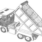 THE TRUCK PAPER
The entire model except for the axles and the engine is made of paper and cardboard. It can make students 3rd-5th grade. The model is like a real machine of the separately mounted parts,...
