I made a root vegetable chopper, so necessary for providing home livestock with vitamin feed (“chopped feed”), based on a decommissioned ATD2—a disc fertilizer spreader that I managed to find among the collective farm scrap metal. Both the metal cylindrical hopper with a lid and lower band, and the working seeding organ itself (simply put, the disc) fit perfectly here.
I detached the band from the base structure. I had to cut out the scale with lever and scraper (the scale was welded); one technological window required a plug, while the other, measuring 100×30 mm, was left unchanged.
Now about the disc (hopper bottom). I removed the agitator and gear from it. In the steel disc, I made a rectangular cutout for the discharge pipe and enlarged the central hole to a size 2 mm larger than the diameter of the electric motor’s output shaft.
As practice has shown, it’s better to use a three-phase motor (1.1 kW, 1450 rpm) with flange connection—it’s easier to attach to the disc. But a single-phase household electric motor with a power of at least 0.9 kW, capable of developing the same rpm, is quite acceptable.
When connecting the selected motor to the disc, naturally, one must not allow the fastening elements to protrude into the hopper cavity. It’s better to use bolts with countersunk heads for a slotted screwdriver here. But welding can also be quite justified.

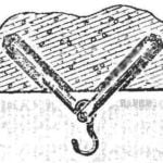
1 — base frame (35×35 angle); 2 — stand (35×35 angle, 4 pcs.); 3 — electric motor (fastening elements not shown); 4 — disc; 5 — hopper with lid; 6 — hub; 7 — chopper knife; 8 — band; 9 — discharge pipe; 10 — brush holder (2 pcs.); 11 — M8 bolt with nut and washer (6 sets); 12 — rubber brush (2 pcs.).
I, for example, “tacked” the electric motor flange to the disc by electric welding through threaded holes, after which I welded the latter to the band. Then I installed the discharge pipe in the cutout on the hopper and welded it at a 30° angle to the vertical, which directs the vitamin “chopped feed” into the receiving bucket during the chopper’s operation. I welded stands to the hopper band from four sides, resting on a square base frame made of 35×35 mm steel angle.
As a blank for such a critical component as the chopper knife, I used a coulter disc from a grain seeder (without the hub), having first reduced its outer diameter to 280 mm, so that when installed in the hopper, a 10-mm working gap would remain between the knife and the band. I reduced the knife diameter using a cutoff abrasive wheel with subsequent edge processing. With the same tool, I also made two narrow radial slots for bending the resulting pair of blades.
I sharpened the chopper knife blades from the hopper lid side. The sharpening angle is 20—30°. And so that the “propeller” shape of the knife wouldn’t change under the pressure of the chopped mass and the blades wouldn’t straighten, I later reinforced them by welding two steel gussets along the disc edge (not shown in the figure).
Two brushes on the rotating disc knife blade sweep the finished “chopped feed” or chaff toward the discharge pipe. Both are made from rubberized belt. Segments of 20×20 mm steel angle welded to the disc from below, as well as M8 bolts with nuts and washers, serve for their attachment. The chopper knife itself is secured to the motor shaft using a homemade hub and key.
The hub was made on a lathe. Its height is such that the knife ends up below the level of the band-to-hopper joint. The keyway in the hub was milled. In the absence of a milling machine, it can be filed with a needle file by hand.
F. SULEIMANOV, innovator
Recommend to read
 SECURE ATTACHMENT
In search of reserves of living space and additional features of the interior, our attention is increasingly attracting ceiling: more and more decisions related to trillenium and slabs.... ELECTRIC VEHICLE “IVOLGA”
"Oriole" — so I called built for the son of the electric car. The design idea came to me about two years ago, and much credit for this journal "modelist-Konstruktor". Several months of...
