I started designing this car a long time ago – maybe ten, maybe fifteen years ago. But this does not mean at all that I stood at the drawing board for all ten to fifteen years. No, I just bit by bit, in the mass of what had already been created and worked out, I was looking for the “golden nuggets” of those unique design solutions that easily fit into the concept of a city car that had already been established for me and the most effective and simple technological methods. And, of course, I brought several of my own ideas into this design – after all, under “others” you will never find in yourself either truly creative powers, or design resourcefulness, or technological resourcefulness.
Of course, at first my requirements for the future car were clearly excessive – this applied to both dimensions and power and, accordingly, to future costs. But over time, the terms of reference, having been reduced to just a few lines, began to look something like this:
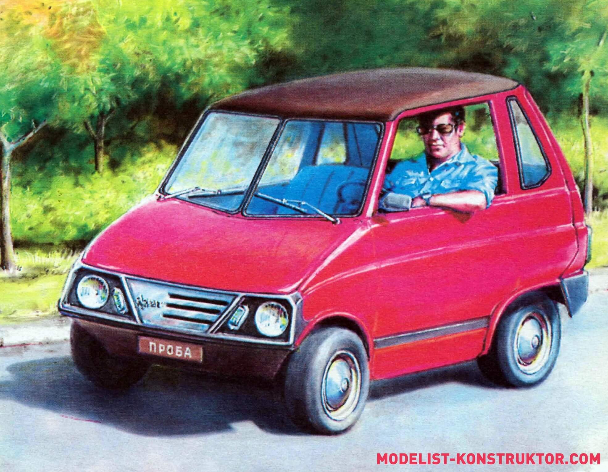
“The machine must be extremely simple so that it can be built without resorting to complex machine tools; as light as possible so that with a relatively low power engine it has good dynamic characteristics; have minimal external dimensions; provide satisfactory comfort to the driver and his only passenger; Finally, the machine must be inexpensive to produce at home and have an attractive appearance.”
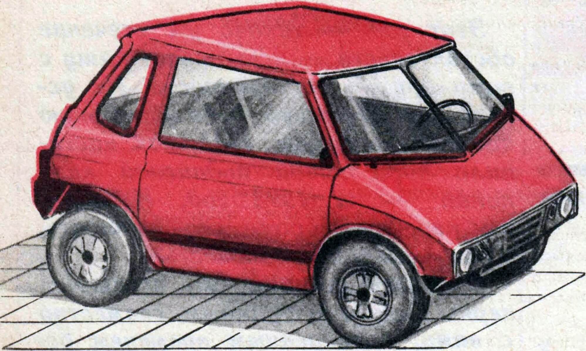
That, in fact, is all the requirements. Based on them, the appearance of this compact and simple two-seater city car, which later received the name “ARBAT,” was gradually created.
***
ENGINE SELECTION . I would be happy to install a small, economical four-stroke engine with a power of about twenty horsepower in my car, but the industry does not yet produce such engines. I had to be content with the Tulitsa engine with a displacement of 200 cm 3 and a power of 14 hp. With. Nevertheless, subsequently I never regretted my choice. Simple, low noise, quite powerful, reliable, and also equipped with a starter engine – what more could you ask for for a homemade product!
SELECTION OF TRANSMISSION SCHEME . Torque from the engine to the rear wheels is usually transmitted in all cars through a differential. From the very beginning, I decided to abandon this heavy and bulky mechanism, and to prevent the tires from “chewing” the rubber when turning, I decided to connect the wheels to the engine through overrunning clutches. True, in this case the car was deprived of reverse gear and the ability to brake with the engine. However, for an ultra-light city car, used mainly in the spring-summer-autumn period, this is not so important.
Structurally, the transmission was planned to be two-stage. From the engine, the torque must be transmitted by a chain to an intermediate central sprocket mounted on a double-sided roller overrunning clutch, and it should cause the axle shaft to rotate. At the ends of the axle shafts there are two more intermediate sprockets, which are connected to the sprockets of the rear wheels by bushing roller chains.
SELECTION OF BODY AND FRAME SCHEME . This task turned out to be especially difficult for me. At first I planned to weld a flat frame, like a go-kart, and install a body on it, glued onto a blank of fiberglass and epoxy resin. But such a design turned out to be unreasonably labor-intensive, complex, heavy, and not very durable.
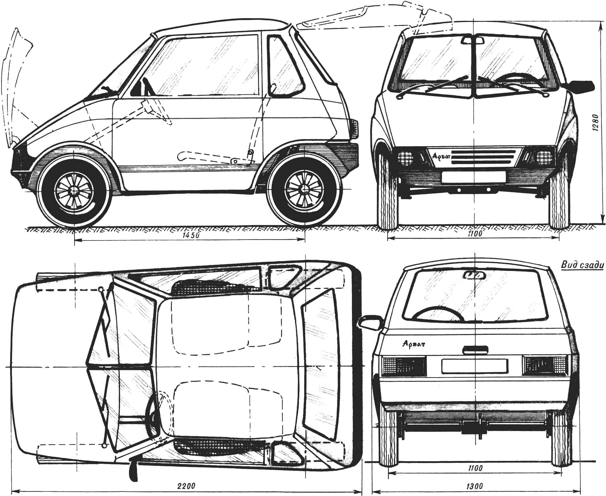
The matter did not move forward until it occurred to me to use two old doors from a VAZ-2105 car as a rigid basis for the body frame. The use of car doors as load-bearing elements also helped in drawing the appearance of the car body – it laid the foundation for its design.
Two doors connected by transverse elements form a rigid box – the basis of the body. True, on my car these doors do not perform their original function: neither the right nor the left open, and the driver and passenger use the only real door – the rear one. As it turned out, for a youth car this arrangement is not only completely acceptable, but also has its own merit: the rear door does not reduce the rigidity of the body, and thus it is possible to significantly reduce the weight of the car by eliminating two massive and durable door frames. The rear door hinges upward – like most modern hatchback cars. The distance between the seats allows passage to both the driver and passenger seats. In addition, each of the chairs has a hinged backrest that folds forward and leans towards the side panel.
SELECTION OF BODY MANUFACTURING TECHNOLOGY . For home use, gluing the body in a matrix or on a block is most acceptable. However, both methods require complex technological equipment, which is sometimes more difficult to make than the actual gluing. Reflections and experiments allowed me to develop an effective matrix-free method for gluing double-curvature fiberglass panels.
Now in more detail and in order about how to make a car similar to my “Arbat” in the conditions of the most primitive workshop. As numerous drawings have shown, the doors of almost any passenger car are quite suitable for the body – in particular, the wide doors of Zaporozhets of any model. I, as already mentioned, got used doors from a Zhigulenka VAZ-2105.
To begin with, I carefully placed both doors on a flat floor and temporarily connected them to each other the way they would be on the future car. Moreover, their mutual orientation, of course, was completely different from that on the VAZ-2105: on the Arbat they have a greater inclination to the floor plane (inward).
Next, I prepared three thin-walled (1.5 mm) pipes with an external Ø 50 mm and fitted them to the lower parts of the doors, one in front and two in the back: the pipes formed the basis of the frame. And two more pipes Ø 30 mm, connecting the upper parts of the doors, closed the structure – a rigid interior box was obtained.
Now it’s the turn of the suspension. On the Arbat, the rear wheels are suspended on longitudinally swinging arms, sprung with the shock absorbers of the Izh-Planet or Izh-Jupiter motorcycle. Each of the suspension arms is hinged in brackets cut from five-millimeter steel sheet and welded to the two rear pipes of the interior box. Swinging – in fluoroplastic or bronze bushings mounted on brackets.
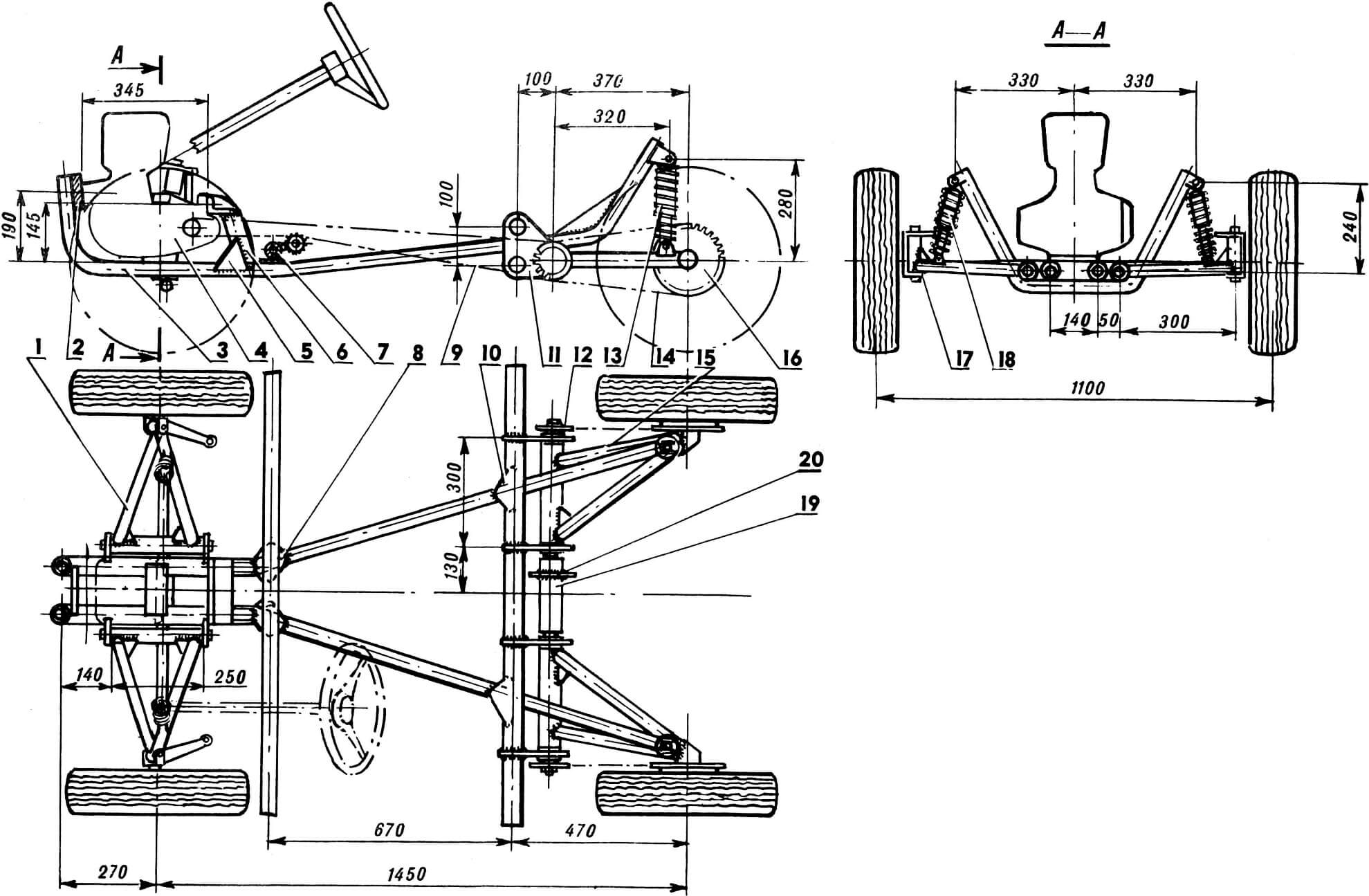
1 — front suspension arm, 2 — front engine mount, 3 — longitudinal frame spar, 4 — T-200 engine, 5 — reinforcing gusset, 6 — rear engine mounting bracket, 7 — front frame cross member, 8 — reinforcing gusset, 9 — first stage bushing-roller chain, 10 — reinforcing gusset, 11 — bracket, 12 — side intermediate sprocket, 13 — shock absorber, 14 — chain, 15 — rear suspension arm, 16 — rear wheel sprocket, 17 — swivel fork, 18 — front suspension shock absorber, 19 — overrunning clutch, 20 — central intermediate sprocket.
To avoid jerking in the transmission, the intermediate shafts and the swing axis of the rear wheels are combined: inside each of the tubular transverse elements of the rear suspension there are intermediate shafts rotating in bearings No. 204. On the outer side of each shaft, an asterisk is secured with screw keys; on the inner side, the shafts are united by a double-sided roller overrunning clutch.
The overrunning clutch itself is a steel bushing with a sprocket welded to it. The mating part of the coupling is the internal parts of the intermediate shafts, on which ledges are milled and blind holes are drilled for the springs.
Related technological advice: in order for the intermediate shafts to be positioned strictly coaxially, it is best to weld the suspension brackets by placing them on a pipe of the appropriate diameter.
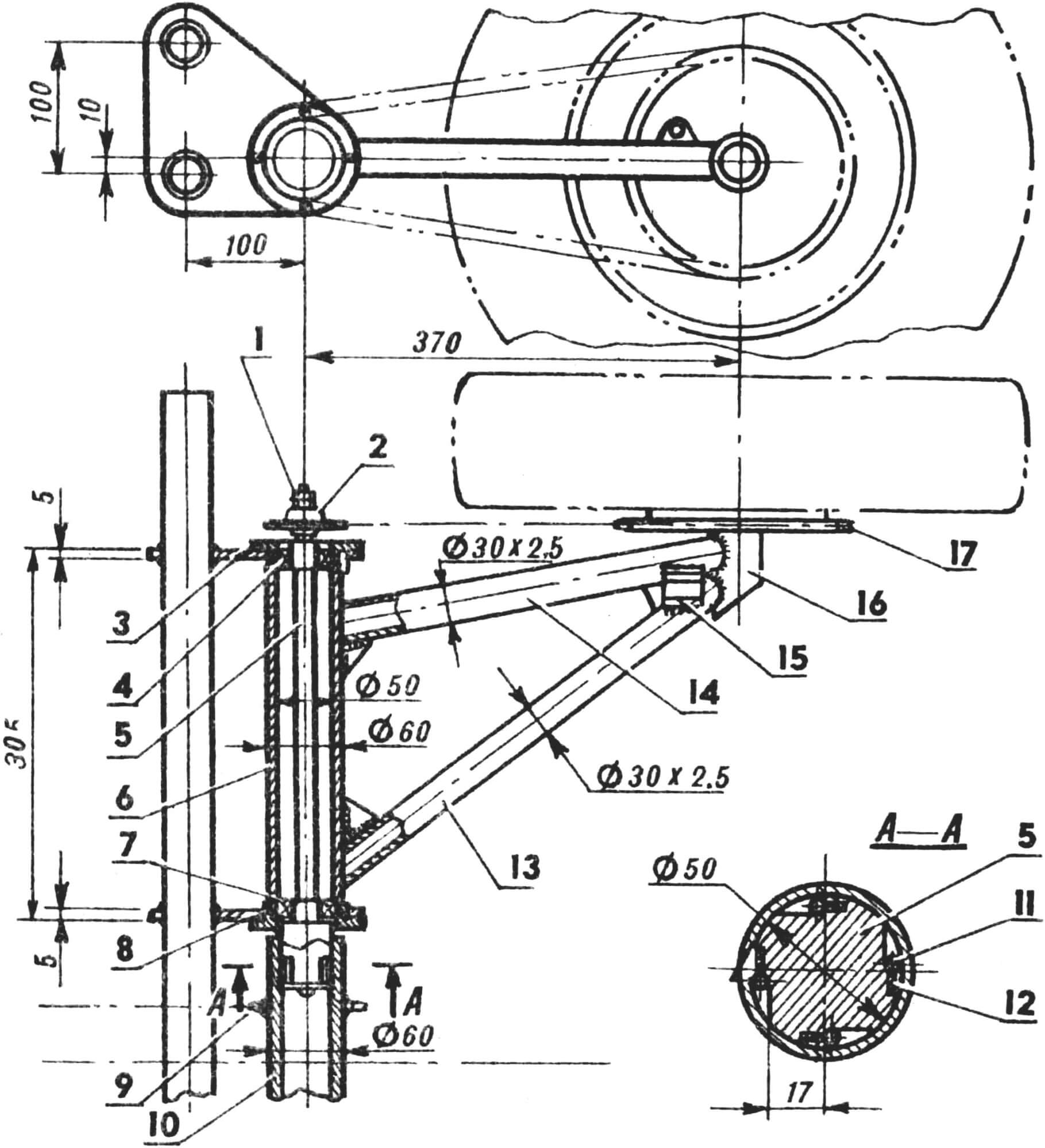
1 – nut and locknut for fastening the intermediate sprocket, 2 – intermediate sprocket, 3 – plain bearing of the suspension arm, 4 – ball bearing (No. 205), 5 – intermediate sprocket shaft, 6 – lever housing, 7 – ball bearing (No. 205), 8 – plain bearing, 9 – intermediate central sprocket, 10 – freewheel housing clutches, 11 — overrunning clutch roller, 12 — spring, 13 — inner tube of the suspension arm, 14 — outer tube of the suspension arm, 15 — suspension shock absorber fork bracket, 16 — axle, 17 — driven sprocket.
The rear suspension arms are welded from two pieces of pipe Ø 30X2 mm and a pipe Ø 52X4 mm. The rear wheel axle is machined according to the model and likeness of the axle of the “Tourist” or “Tulitsa” scooter.
The longitudinal frame spars are bent using a pipe bender with the pipes pre-filled with sifted sand. They are welded to the transverse beams using reinforcing gussets made of 2 mm thick steel sheet. It is advisable to install the rear and front engine mounting units “in place” – with preliminary adjustment of the brackets, fixing them on the engine, tack welding with several welding points, and after removing the engine – final welding of the plates and brackets. The forks in which the rear suspension shock absorbers are installed should be welded in the same way.
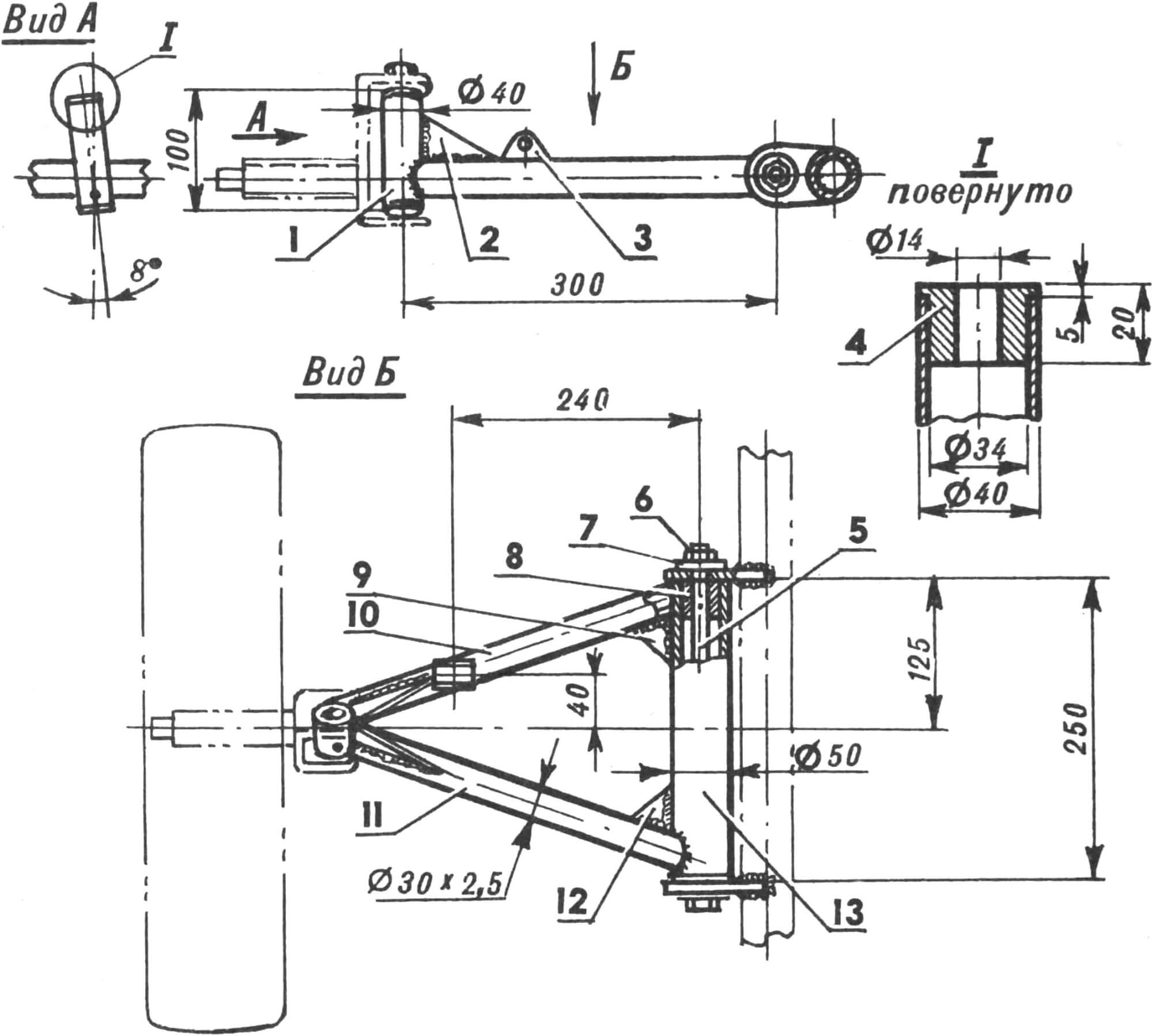
1 – wheel swivel fork hinge, 2 – gusset, 3 – suspension shock absorber fork bracket, 4 – bronze bushing, 5 – rocker axle, 6 – suspension axle nut, 7 – washer, 8 – bronze bushing, 9 – gusset, 10 – front lever tube, 11 – rear lever tube, 12 — gusset, 13 — lever body.
The front suspension of the car is with transverse swing arms and suspension with motorcycle-type shock absorbers. The suspension arm brackets are similar to the rear ones; however, they are welded to the longitudinal frame members. The suspension joints are equipped with inserts – bronze or fluoroplastic.
The rack and pinion steering mechanism is from an SZD motorized stroller. The swivel forks are cut from sections of steel channel together with the swivel arm. The front axle shafts are machined, their dimensions and configuration must correspond to the standard axles of the scooter. They are attached to the rotary forks by welding, as shown in the pictures. Bronze (possibly fluoroplastic) bushings are pressed into the fixed fists. The axle is a long bolt, seated tightly in the fork and sliding along it into the bushings of the fists.
A little about the manufacturing technology of fiberglass panels for the body. In principle, it is not difficult. First of all, a frame is bent from a duralumin or steel pipe of a suitable diameter (10…15 mm), which represents the exact outline of the future panel, and is carefully adjusted along its parting line with the rest of the body panels. Next, the frame is fixed strictly horizontally (for example, suspended on four pieces of strong twine from the ceiling) and a fiberglass panel is glued to it with a “Moment” or grabbed with threads. It is advisable to use the thickest possible fabric for this purpose – for example, glass matting. This operation is very responsible, so I advise you not to waste time on it. The fact is that the fabric on the frame should not be fastened tightly, but so that it sag slightly and forms a convex surface of double curvature. It is advisable to control yourself with templates – especially when it comes to such large panels as the roof or hood. By tightening or loosening the tension of the material, you can achieve the planned curvature – after all, the force of gravity in conjunction with the tension force will arrange the fabric along the so-called “caten lines”.
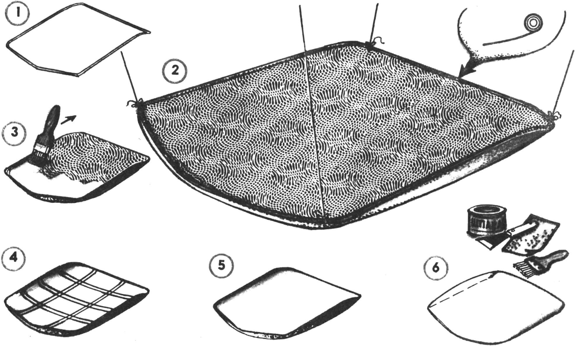
1 – making a tubular frame, 2 – hanging the frame and basting a fabric base to the frame, 3 – applying epoxy resin to the fabric, 4 – gluing foam filling, 5 – gluing with fabric on epoxy resin, 6 – finishing operations – puttying, sanding, priming.
Now you should dilute the epoxy resin with the hardener in the ratio specified in the instructions attached to the package, and then dilute it with acetone so that its consistency makes it possible to use a spray bottle. The first “spraying” should be such that the fiberglass fabric is only slightly moistened. A fabric soaked in resin may lose its given shape, so try to make some adjustments to the shape of the future panel while the epoxy has not completely hardened.
If there is a need to create ribs or ridges on the panel, this must be taken into account when preparing the frame by introducing smoothly curved slats into it from the inside (if the edge is supposed to be convex), or by pulling one or more threads from the outside (if concavity is required).
When the first layer is partially polymerized (this will happen after 4-6 hours), apply another one to the fabric, and if after that all the pores of the fabric are closed, apply subsequent layers with a resin of normal consistency, without diluting it with acetone.
After these operations, the shell, as a rule, acquires strength sufficient to proceed to the next stage – gluing the panel from the inside with foam plastic.
Prepare foam plastic “straws” – slats with a cross section of 15X30 mm. Construction or packaging foam is suitable for this. It is best to cut it into slats with a nichrome string heated by electric current.
Carefully cover the inside of the panel with “straws”. It is advisable to first fix two to four slats, and when the epoxy has hardened, glue the rest. Finally, the foam surface is leveled and covered with a layer of fiberglass.
It is easy to attach such panels to the frame pipes, which are a strong and rigid flange – for this, holes are drilled in the tube and threads are cut into them. It is also advisable to tighten the mounting screws in them using epoxy glue.
The inside of the ceiling panel is covered with decorative material – fabric, leatherette or artificial leather.
Using this method, you can glue almost all body panels – including the back door, the hood, the fenders, and the side panels. Only the front part of a rather complex shape and the rear bumper were molded from a blank.
Leveling the panels with epoxy putty. If you can’t buy it, mix epoxy with tooth powder or talcum powder. Final finishing is done with hot-drying synthetic enamel.
The seats in Arbat are homemade. Each is a frame made of duralumin pipes (from the “clamshell”), covered with a polyvinyl tube. A chair of this type has good shock-absorbing properties and is very light in weight. As already mentioned, the back of each seat can recline forward, and the entire seat can be swiveled to the side of the cabin. This design makes it relatively easy to get in and out of the cabin through a single door.
The floor in the cabin is cut from aluminum sheet. Near the longitudinal axis, a casing is fixed to the floor, inside which a bushing-roller transmission chain passes.
Fuel tanks (there are two of them) are located directly above the engine, in the area of the so-called “dashboard”. The tank capacity is 10 liters – this is quite enough for city driving. The filler necks are hidden under the hood. It is convenient to use factory-made tanks – for example, from the Riga-11 moped.
The instrument panel is equipped with a standard scooter speedometer, an ignition-on warning lamp, and turn signal and brake light repeaters. Headlight switches, turn signal switches and a scooter ignition switch are also mounted there.
In conclusion, it should be noted that, in my opinion, the car turned out to be successful – dynamic, fairly light, moderately fast, economical. In any case, on the street I feel like a driver not of a slow-moving wheelchair, but of a fairly “nimble” car. I think that among the readers of “M-K” there will be those who want to reproduce the design of my “Arbat” – just please do not repeat “literally”. You will still learn something from your mistakes, but it’s unlikely that you will learn from mine. And today I would not have designed this car in the form in which I presented it on the pages of the magazine. But these are thoughts about the future.
N. IONOV, engineer
Recommend to read
 FOR A SAILBOAT SKIING
When going on a long journey, skier, usually relying only on its own strength. However, it is possible to summon the wind, erecting for this purpose a sailing ship. To collect such...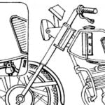 HOW MANY IN THE TANK?
This question continues to torment motorcyclists — and this despite the fact that the "modelist-Konstruktor" on their pages several times already talked about the interesting enough the...
