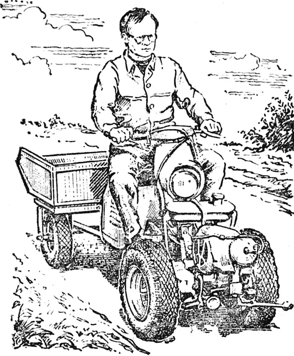
The walk-behind tractor was built by members of the “Young Technician” club of Vocational School No. 25 from the city of Kelmency, Chernivtsi region. With its help, they cultivate potato plots, mow grass, and transport cargo.
The walk-behind tractor’s layout is traditional: frame, engine, and two-wheeled running gear. As needed, the following are attached to it: in front — a mower with drive from the power take-off shaft; in the rear — a single-body plow with a support wheel; three tine cultivator shanks or a harrow (via the hitch device); a cargo cart (via a hinge joint).
As in many similar machines, the walk-behind tractor and cart construction uses components and assemblies from the “Vyatka” and “Elektron” motor scooters. These are the VP-150M engine, wheels, frame, handlebar, electrical equipment instruments, and seat. The wheels are taken from a decommissioned cultivator, the conical reducer for the conveyor shaft drive, cutting apparatus, and reel — from the ZhVN-6 harvester, overrunning clutches — from the SZUG-3, 6 grain seeder, fuel tank — from the starting engine of the YuMZ-6 tractor.
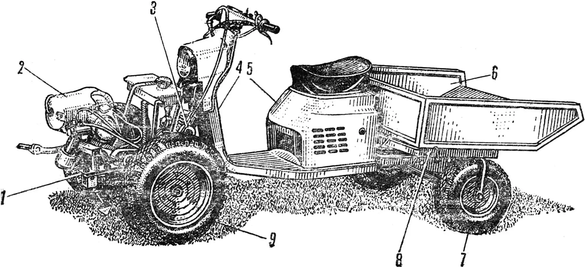
1 — walk-behind tractor frame, 2 — VP-150M engine, 3 — cart attachment hinge joint, 4 — motor scooter frame, 5 — shortened engine housing, 6 — cargo body, 7 — motor scooter wheel, 8 — cart subframe, 9 — cultivator wheel.
The walk-behind tractor’s transmission is mechanical, gear-chain type. It consists of two sprockets with 10 and 44 teeth, a chain with a 19.05 mm pitch, and a pair of bevel gears with a 1.4 gear ratio on the power take-off shaft, extended forward.
The differential was abandoned in the transmission, as this would have required introducing a wheel locking mechanism, which, first, complicates the construction, and second, makes maneuvering on small plots difficult.
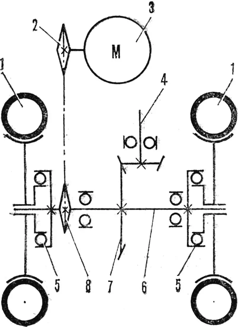
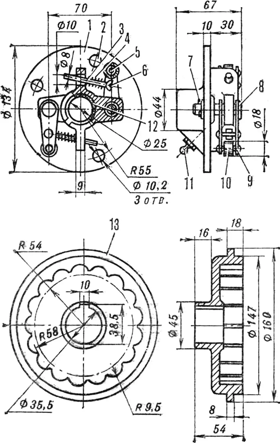
1 — wheels, 2 — drive sprocket (z=10), 3 — engine, 4 — power take-off shaft, 5 — overrunning clutches, 6 — running shaft, 7 — reducer, 8 — driven sprocket (z=44).
Therefore, two overrunning clutches were used, which allow the drive wheels to slip.
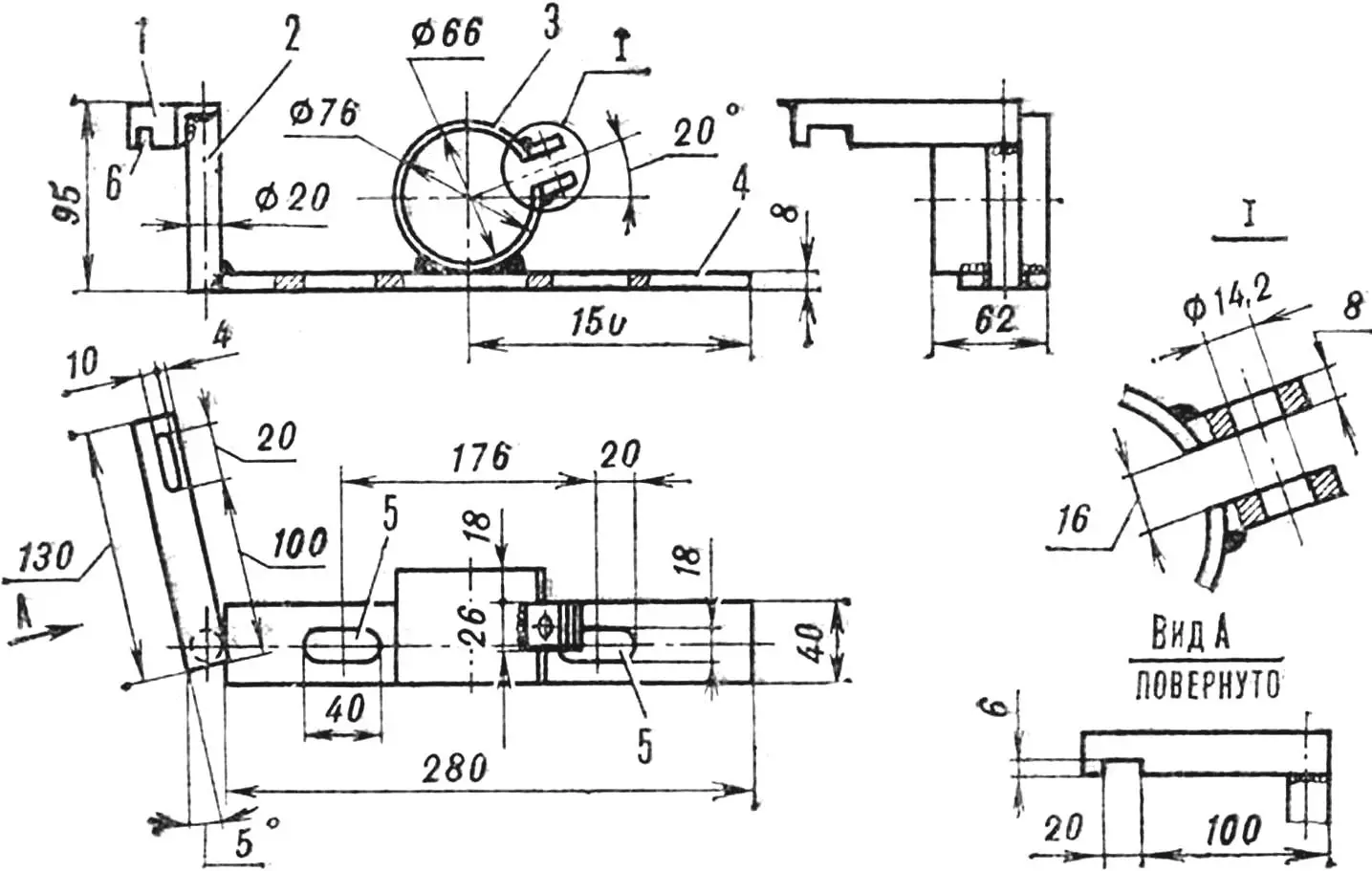
The walk-behind tractor’s power unit is the frame (fig. 3). Its base is a cross member — a 75X40 mm angle, in which four holes are drilled: two Ø 14.2 and two Ø 12.2 mm. Two M12 bolts are welded into the latter from the inner side of the frame. They serve to attach the agricultural implement hitch device and the cargo cart hinge joint.
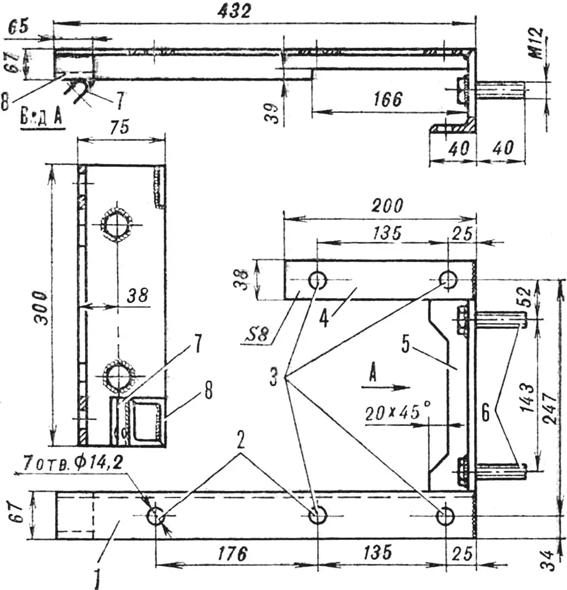
1 — support beam, 2 — engine subframe mounting holes, 3 — reducer mounting holes, 4 — support plate, 5 — cross member, 6 — hitch device and cart connection bolts, 7 — parking stand bracket, 8 — bracket support.
A support beam — a 67X67 mm angle with a 166X39 mm cutout in the vertical flange for the reducer housing — is welded to the left of the cross member. At the front, the beam ends with the parking stand bracket support.
A support plate measuring 200Х38Х8 mm, intended, like the beam, for mounting the reducer, is welded to the right of the cross member.
The engine subframe (fig. 5) is a plate measuring 280X40X8 mm, to the middle of which an engine mounting clamp made from a 76X5 mm pipe is welded. Oblong holes are also made here for tensioning the drive chain by moving the entire engine subframe relative to the walk-behind tractor frame.
1 — front engine mounting bracket, 2 — rod, 3 — clamp, 4 — plate, 5 — engine subframe mounting and drive chain tensioning holes, 6 — clutch cable housing mounting cutout.
A vertical rod — a Ø 20 mm bar — is welded to the front of the plate, and to it — the front engine mounting bracket — a 20X20 mm angle with a longitudinal hole in the horizontal flange, which serves to adjust the engine position on the frame and eliminate chain misalignment. A 20X6 mm cutout is made in the vertical flange of the angle for installing the clutch cable housing stop.
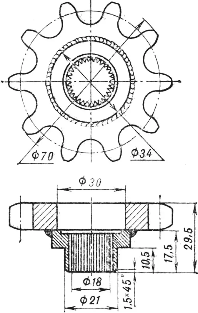
The torque from the output shaft is transmitted to the chain by the drive sprocket. It is made from a hub — an old sprocket from the “Vyatka” motor scooter, the teeth of which are ground down to Ø 34 mm — and a ten-tooth sprocket with a central hole Ø 30 mm. They are welded together, as shown in figure 4.
In assembled form, the walk-behind tractor is compact. To further reduce its dimensions, the standard motor scooter engine muffler was replaced with a homemade, more compact one (fig. 13), which is in no way inferior to the factory one in terms of performance. For its manufacture, part of the “Vyatka” muffler was used — a pipe with a band. It is inserted into a Ø 75 and 65 mm high cup and connected to a ring by welding. A hole is drilled in the cup for exhaust gas outlet. The muffler is installed directly on the engine cylinder exhaust port.
The engine is started, as on a motor scooter, with a kickstarter. Fuel flows to the carburetor by gravity. Gear shifting is performed by a lever welded to the gearbox sector.
However, the main walk-behind tractor controls — throttle and clutch levers — are extended to the hitch device control handles and the cargo cart handlebar.
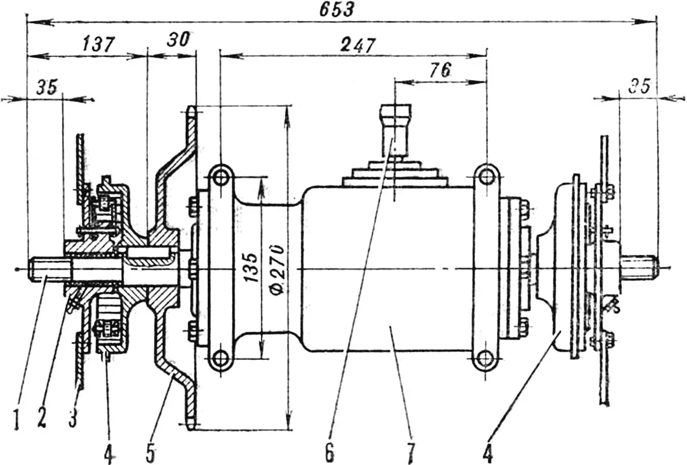
1 — running shaft, 2 — overrunning clutch driven part, 3 — wheel disk, 4 — clutch drive parts, 5 — driven sprocket (z=44), 6 — power take-off shaft, 7 — reducer.
The walk-behind tractor bridge is shown in figure 6. To install the overrunning clutches, the reducer shaft had to be extended by 170 mm (100 mm on the left and 70 mm on the right). For this, central holes Ø 8 and 30 mm deep are drilled in its ends and M10 thread is cut. Rods 130 and 100 mm long are screwed in there, welded to the shaft, turned to Ø 25 mm, and M20 thread 40 mm long is cut on the ends. Holes Ø 3.2 mm are drilled for cotter pins.
A driven sprocket with 44 teeth and the drive part of the left overrunning clutch are installed on the left end of the shaft on a common key (for this, its mounting surface was turned to Ø 35.5 mm and a keyway was milled). The same keyway was made on the right side of the shaft.
The driven parts of the clutches were not modified, only three holes were drilled in them for mounting the cultivator wheel disks.
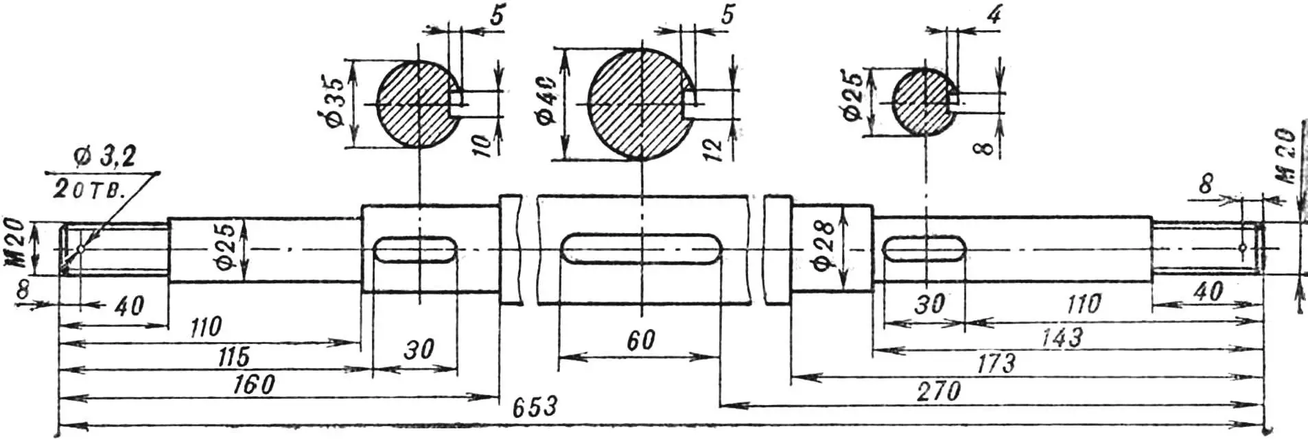
Of course, if desired, a new running shaft could be made, it is shown in figure 7.
The overrunning clutch (fig. 8) works as follows. When the shaft rotates, the drive part with its cells presses against the driven part’s roller and forces it to rotate. When the walk-behind tractor turns, the wheel moving along a circle of larger radius rotates faster than the shaft, and the clutch drive part, accordingly, faster than the driven part. Therefore, the rollers, compressing the springs, skip over the cell surface (quiet clicks are heard). When the wheel rotation speed decreases, the rollers re-engage with the cells.
1 — driven part, 2 — hole for mounting to wheel disk, 3 — guide rod, 4 — spring, 5 — roller axis, 6 — stop, 7 — cotter pin, 8 — plate axis, 9 — plate, 10 — roller, 11 — grease fitting, 12 — nylon bushing, 13 — drive part.
A nylon bushing is pressed into the inner cavity of each overrunning clutch’s driven part. The “running shaft—bushing” connection is lubricated with grease through a grease fitting.
For the hitch device (fig. 9), cultivator units were used. The double drawbars are shortened and welded to the connection channel. Longitudinal holes for mounting to the walk-behind tractor are also made in it.
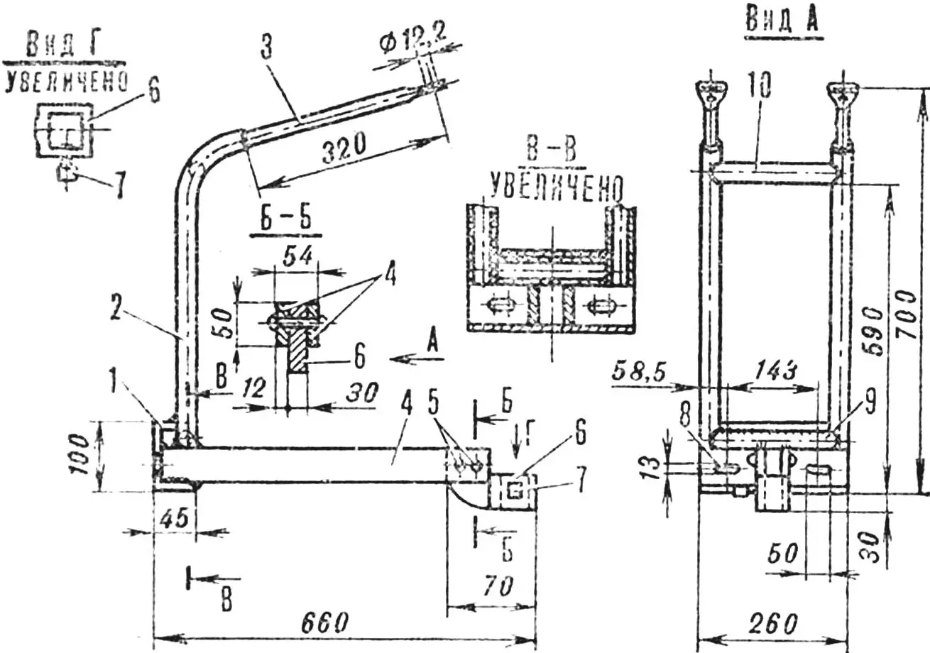
1 — connection channel, 2, 3 — handle tubes, 4 — drawbars, 5 — rivets, 6 — agricultural implement holder bracket, 7 — stop screw, 8 — walk-behind tractor frame connection hole, 9, 10 — crosspieces.
The drawbars end with a bracket—agricultural implement holder with a hole for their posts and a stop screw.
Control handle tubes are welded to the top of the channel. Their ends are flattened, and holes are drilled in them for installing the handlebar with throttle and clutch levers.
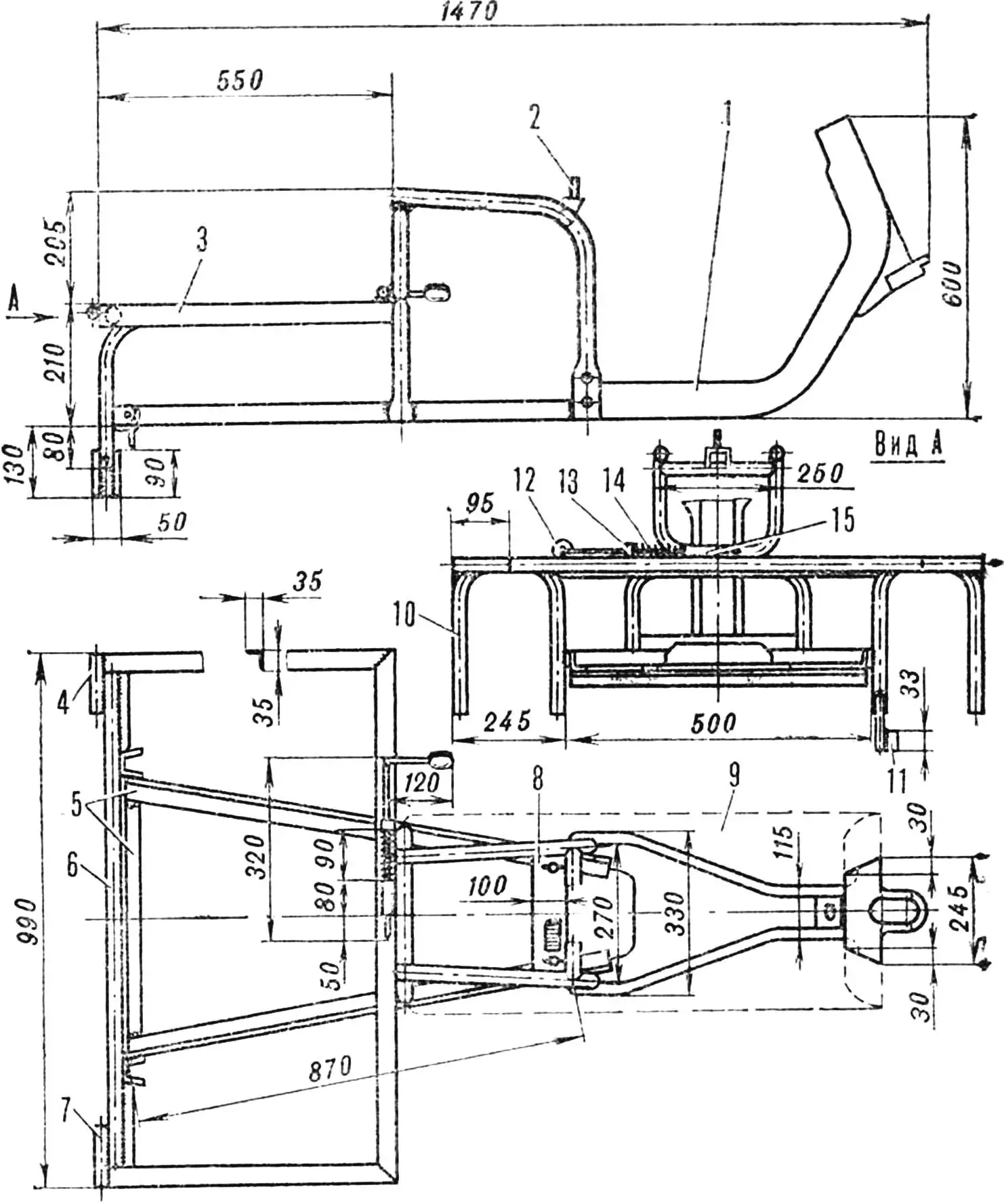
1 — angle frame, 2 — side sheathing, 3, 6 — cart frame mounting hinges, 4 — support angle, 5 — bottom.
The hinge joint (fig. 12) is made from the motor scooter steering shaft. The shaft is shortened to 460 mm, and a car driveshaft hinge fork is welded to it from below. The mating fork is removed, and plates 135 mm long are put on and welded to the cross ends. The lower ends of the plates are beveled and welded to the channel. Longitudinal holes for mounting the cart to the walk-behind tractor frame are also made in the latter. The hinge joint is lubricated through a grease fitting.

1 — motor scooter frame, 2 — seat stud, 3 — subframe, 4, 7 — body hitch bushings, 5 — additional 35X35 mm angles, 6 — subframe tube, 8 — adjustment plate, 9 — removed motor scooter body part, 10 — wheel fork, 11 — brake drum housing stop, 12 — lock lever, 13 — eye, 14 — spring, 15 — guide bushing.
The cart frame (fig. 11) is based on the “Vyatka” or “Elektron” motor scooter frame. Two 35X35 mm angles 870 mm long each are welded to it from below. Their rear free ends are connected by a third angle 500 mm long. Here also are two forks from the “Vyatka” front suspension (the brake drum housing stop is welded into the right one), connected to each other by a horizontal half-inch tube. A U-shaped subframe made of 35X35 mm angles is also welded to it and to the main motor scooter frame. Two hitch bushings are attached to the horizontal tube for mounting the body.
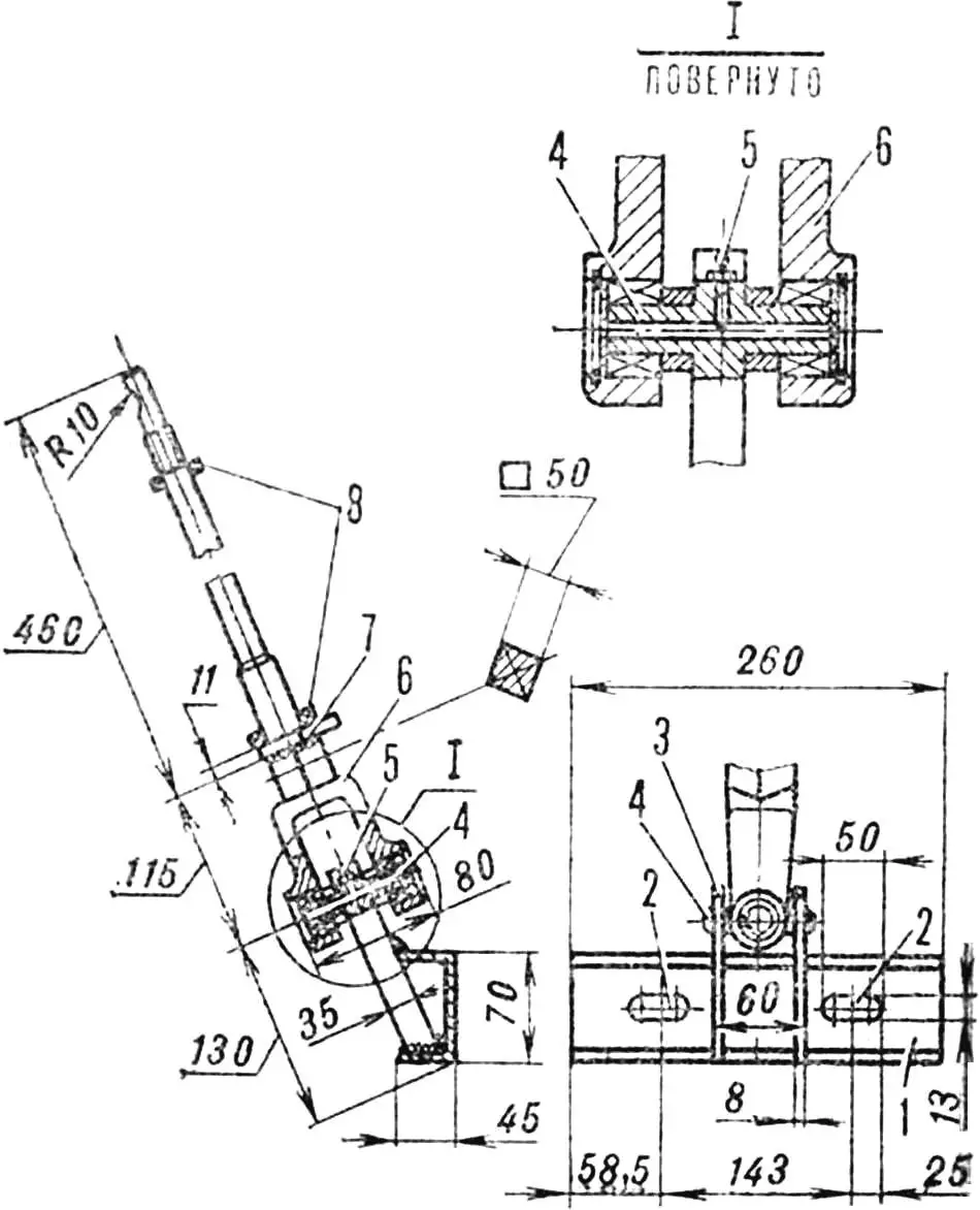
1 — channel, 2 — walk-behind tractor frame mounting holes, 3 — plate, 4 — cross, 5 — grease fitting, 6 — fork, 7 — steering shaft shortening location, 8 — ball bearings.
A simple body locking mechanism is installed on the subframe’s transverse angle: lock lever, eye, spring, and guide bushing. At a distance of 190 mm from the lock lever handle, a Ø 2.5 mm hole is drilled and a cotter pin is inserted, against which the spring rests. In the working position, the lock enters the front body mounting loop with its point and holds it.
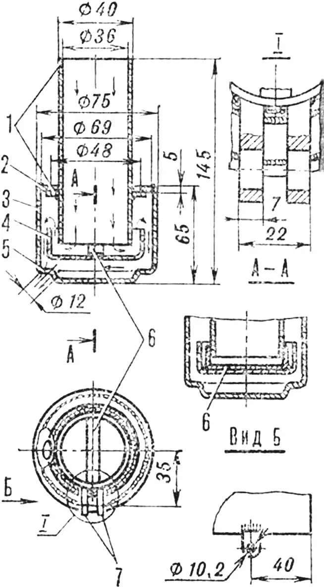
1 — pipe with band, 2 — ring, 3 — cup, 4 — reflector, 5 — exhaust port, 6 — reflector bracket, 7 — additional mounting loops.
The cart body frame (fig. 10) is made of 20X20 mm angles and sheathed with 1.5 mm thick sheet steel. A loop for fixing the body in transport position is welded to its front, and on the sides — connection loops with hitch bushings, where pins — steel rods Ø 17 mm — are inserted.
In conclusion, it remains to say that operating the walk-behind tractor is simple. Members of our club, for example, master it in one session. The walk-behind tractor is also convenient for transporting cargo. The driver is positioned on a shortened and rotated 180° seat (with a tool box underneath) and controls the walk-behind tractor, holding onto the standard handles left on the handlebar.
WALK-BEHIND TRACTOR TECHNICAL DATA
Length, mm … 900
Width, mm … 670
Height, mm … 900
Weight, kgf … 65
Maximum speed, km/h … 18
Track, mm … 550
Trailer cart track, mm … 750
Walk-behind tractor with cart wheelbase, mm … 1580
Minimum turning radius of walk-behind tractor with cart, mm … 200
V. MYKYTYUK, club leader
Recommend to read
 “GODDESS”, THE CHARACTERS AND SYMBOLS
Few ocean giants — "Rurik", Gromoboy and Rossiya, though it presented a menace to navigation "ancestral enemy" — Britain in the case seemed such a possible war, but the scale of such...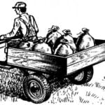 RELIABLE ASSISTANT TILLERS
Continue the story of machines and mechanisms, built by V. A. VERBELEN — Amateur designer from the village of Zelenchukskaya, Karachayevo-Cherkess Republic. In the publication...
