AT THE ELITE

THE ELITE
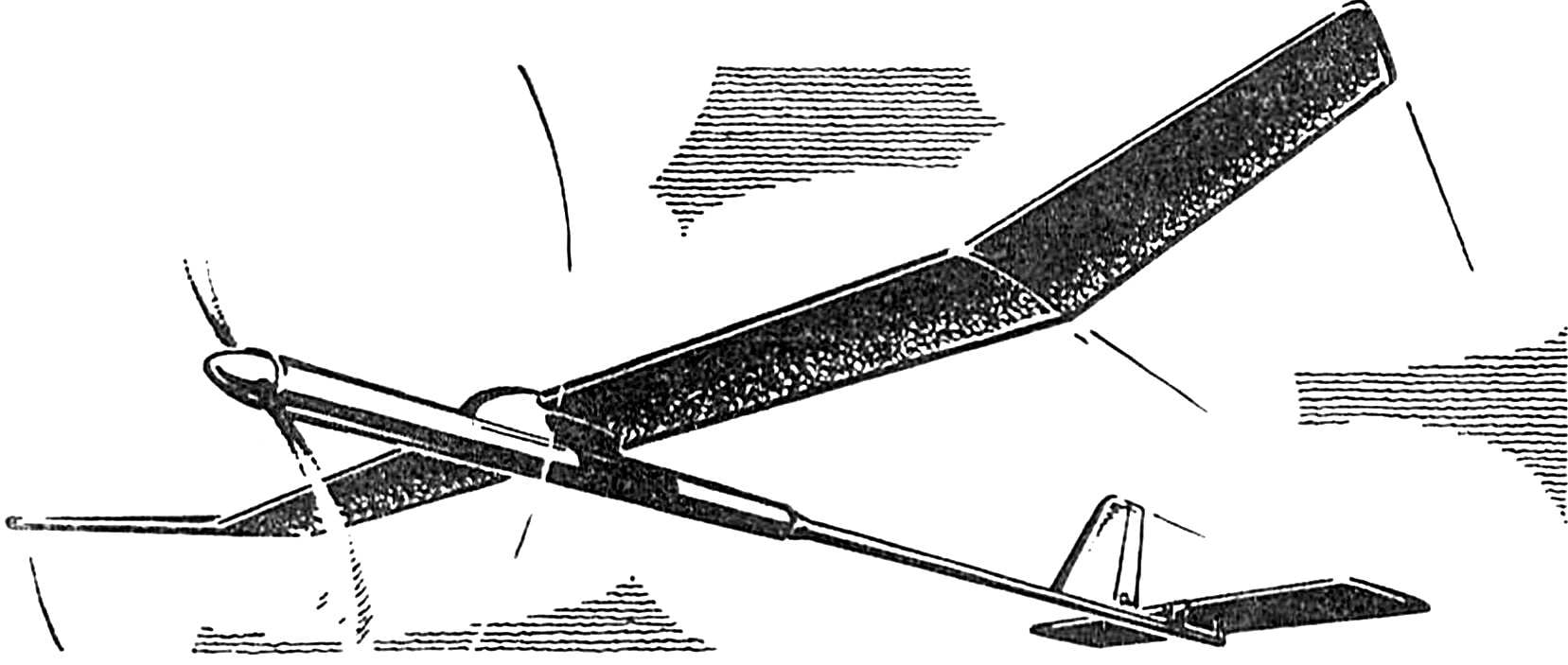
We offer rezinomotornaya model class F1B developed by the head of the laboratory he is the eldest Nizhny Novgorod, candidate of master of sports of the USSR by I. Gorkinym. The basis of her design was based on the scheme of the deserved master of sports, repeated world champion aandryukova, which is due to a number of technical and technological solutions has been made more accessible to repetition.
For example, the boss removed capricious in manufacturing and operation (especially from the point of view of ordinary modelers) node feathering of the blades and hook. The shaft is machined from a titanium alloy. Along with the use of dural coil is provided a gain in mass of 1.5 g. Duralumin sleeve, insert blades, replaced by pins, which was very convenient for practice. Tail boom because of its long length made from carbon at well-built from model aircraft technology.
 
The shoulder model is considerably increased. Pilon made a new form; 3-5 g reduced weight of the wing while increasing its strength. Last used ribs from balsa trim platinu, balsa edges (and rear — platinovoi pasting). Rails — tubular, Stekloplastik.
 
As shown, such designs work well on all types of deformations. Also have a weight advantage. As, however, and the carbon fiber seatpost that protect the wing from damage due to sudden impact with the ground.
 
The unusual design has a stabilizer. Unwittingly draws the attention of a one-piece spar of balsa, located on edge and covered with platinu. Rib oblique, split. Butt glued to the spar and leading edge. At the rear edge of embedded.
 
The rubber motor of the domestic rubber with silicone grease.
 
This model fully meets the requirements of the FAI to F1B. This means that the carrier surface rezinomotornaya 17…19 DM2, the minimum weight of the model 230 Gauss, the maximum load of 50 GF/DM2, weight lubricated motor not exceeding 40 GS.
 
Speaking at the event in Nizhny Novgorod, the author and the developer became the champion of the region, gaining a total of 1167 points.
Risky, of course, to generalize, but currently almost all technical sports mass, it seems, gives way to elitism. Even the technique itself, which are competing for the Republican (and especially a Union and higher) level, often inaccessible difficult for the athlete from the periphery. And rezinomotornaya class F1B model aircraft here, alas, is no exception.
 
But the hopeless situations does not happen. You can, for example, by results of processing of the average parameters and the “average” technology by design model. It is also possible that at some time it will be even in a winning position. Only better, I think, another way to choose promising, according to experts, a design, to analyze it. To find (taking into account the recommendations of the science and practice of amendments to “local conditions”) the possibility of its recurrence in a way acceptable to you the option to include their findings and technical decisions.
 
In this way, and we went in this case, choosing a basis popular among modelers scheme aandryukova. The resulting model (see illustration) has good performance, easily “replicated”, including in the periphery. Technology (and this is easily seen) is relatively simple. And set out in the order in which the rational and the model manufacturing.
 
The wing is detachable, profile Ge-495. To start manufacture it is advisable, in our opinion, the spar on the center section. And design is at the root of the bushing (internal diameter 6 mm, width 2 mm, wall thickness 0.3 mm) of titanium. The technology basically known to those who had the opportunity to carry out tubular parts from dissimilar materials, impregnated with epoxy. But now the mandrel is taken with cone. Its length is 480 mm, and the diameters at the ends — 6 mm and 5 mm.
 
Such a mandrel is pre-coated with two layers of soap, is wound (overlapping turns) on a spiral path Mylar film with a thickness of 0,03 mm. This will then facilitate eat the finished product. Then superimposed to 0.03 mm aluminum foil, cut in the form of a right trapezoid with a height of 480 mm and bases of 25 mm and 20 mm. For convenience, maintain the shape all wrapped Kevlar thread. The FRP sheets with a thickness of 0.08 mm, carved in the form of a trapezoid (of size 480X50X40 mm) and impregnated with a mixture of resins brands of ED-20 and C-153 in equal proportions, overlayed on top in two layers. A third, optional (trapezoid 160Х25Х22 mm 0,08 mm carbon fabric) — length 160 mm at the root of the spar. All of this closes the astrolon 0.4 mm thick and wrapped with two layers of rubber strap.
 
General view of the model.
 
After curing, epoxy resin spar is processed on a lathe with sandpaper and then removed from the mandrel. Moreover, if the weight of the product is initially 5.3 to 5.6 g, then after turning is reduced to 5.2 to 5.5 g.
 
The spar on the “ear” of the wing is made the same way. Take the same materials, but, of course, several other dimensions to the structure of the wall along the entire length of the “ear” repeated the end part of layerone of center. And this is possible only when the following amounts of trapezoids: D16T — 315X20X14 mm, carbon — 315X40X30 mm, astrolon — 315X22X20 mm. Weight of the finished product 2,2—2,4 g.
 
For wing leading edges take the balsa with density of 0.1 g/cm3. In a rail section 4X4 mm this material is on the front edge. With back harder. Rake here a conical section 3,5X1,5X1 mm and a length of 480 mm, moreover, is glued on two sides of 0.08 mm platinu. The mass of the trailing edge of the wing — 1,1—1,2 g, “ear” — 0.6 g.
 
The balsa of the same density is on the ribs. Pre-cut them as a single unit from bar thickness 33-35 mm two templates, applied laterally. Made bundle, which is subsequently glued platinu thickness 0.08 mm on both sides. After solidification of the resin drilled hole of the minimum diameter of the spar. Pack of sawn 1-mm milling cutter on the machine “Skillful hands”. The finished ribs are adjusted with a tapered file to the spar individually. The mass of the ribs on the center section after cutting 2.3 to 2.5 g (15 PCs.), on the “ear” is 1.3 — 1.5 g (9 pieces), the latter are made in the same way.
 
The wing Assembly is carried out at a drawing pinned on a flat bench. Spar finally adjusted the rib. Individually according to the drawing cut into each rib with a scalpel trailing edge. Completed the first phase of the Assembly by gluing the ribs to the spar and trailing edge. The second stage is usually sticking to the leading edge. And the third — pasted and eskoriatza the profile braces (weight 3.5 g). Then the center section fit in with the “ear” epoxy resin using area, is made of mm plywood and glued in the spar. The mass of the two (“broshennyh”) half wing with this technology of manufacture will not exceed 36-38 G.
 
Then the wing is covered with three layers of glue “Moment”, diluted with solvent in the ratio 1:2. Metallized polyester with a thickness of 0.015 mm is used as plating. Glued it to contour to the ribs, then stretch film and a fix for occasional distortions of the wing. Not hurt, I think, here and additional control over the increase in weight of the product. When properly stitched Dacron wing with the weight gain should not exceed 7 g.
 
To give the skin additional related turbulence qualities, used Japanese paper with a thickness of 0,04 mm. Taping it is built on top of the metalized polyester caponline. But only the top wing from the leading edge to the spar. And at a distance of 6 mm from the beginning of the leading edge of the wing is fixed on Amalia and the baffle diameter of 0.4 mm. the total weight of the product it will add 3 more g — payback for a high aerodynamic quality of the model.
 
The stabilizer has a popular for this class of models profile Clark Y 6%. The peculiarity of this particular design is that the spar here is a balsa (density 0.07 g/cm3) rail cross-section 5X2 mm, placed with the edge up and pasted 0,08 mm platinu. And pasting — in a single layer and only in the center of the length of 80 mm in two layers. The mass of the spar 0.6 g.
 
From the same balsa are (but without pasting ogladania) scarves, ending and Central rib. The last mass of 0.27 g. Spouts (0.6—0.8 g) pre-manufactured as a single block of balsa block with a density of 0.08 g/cm3 for the two templates, applied laterally, and subsequent sawing. Similarly performed, by the way, and braces.
 
But the source material (thus weight) is different from the spouts. In particular, the front braces are made from balsa with a density of 0.07 g/cm3, and the rear — 0,1 g/cm3.
 
The leading edge as the wing, almost no grind. Weight 0.5 g Material — balsa with a density of 0.22 g/cm3. The rear edge obecna. Made of balsa with a density of 0.28 g/cm3 and has a mass of 0.57 g.
 
The Assembly of the stabilizer is carried out according to the drawing, mounted directly on the stocks. Gluing is performed in two stages. The first is according to the formula: spar + spouts + ending + Central rib + front edge. In the second stage, stick the struts and the trailing edge. Followed by sanding, after which the mass of the stabilizer becomes equal to 2.1 g But the cording adds their “Mylar grams”. As, however, add hooks, bushings, increased front edge by 20 mm at the center of the fiberglass thickness 0.05 mm, increased under the three-minute cravings.
 
Tail boom with a keel pad lock flight and the rudder also has its constructive and technological features. First of all, a good, according to practitioners and judges, the use of the composite, which greatly simplifies the entire structure while increasing its stiffness, reliability in operation. One of the first descriptions of the technology of composite tail boom, I remember, appeared in the fourth issue of “M-K” for 1988. The difference between the proposed variant the size cone mandrel (770X10,5X6 mm) and used as the basis materials.
 
Tail boom Assembly with the fin and stabilizer.
Tail boom Assembly with the fin and stabilizer:
1 — bushing adapter (D16T), 2 — tail boom, 3 — rods, 4 — Kiel, a 5 — rudder, 6 — celluloid insert, 7 — emphasis-base, 8 — pole (D16T), 9 — kordovye guides, 10 — thrust stabilizer, 11 — bolt-limiter (M2, caprolon), 12 — stabilizer, 13 — a bolt of fungus (M2, caprolon), 14 — nut fungus (M2, caprolon), 15 — rubber thread attachment of the stabilizer pole 16 — screw M1,6 (motor. flight, 2nd team), 17 — screw M1,6 (motor. flight, 1st team), 18 — screw M1,6 (planir. flight), 19 — pylon (D16T).
 
The conditional contour line shows the position of the stabilizer on parasuraman.
 
Table of coordinates.

 
As in the case of a wing spar, you will need 0,03 mm Mylar film in the form of a trapezoid, but the size 1000Х35Х18 mm. It is wound on a spiral path covered with two layers of soap mandrel. Then along the entire length of the future tail boom in two layers superimposed trapezoidal blank (750X72X43 mm) made of 0.15-mm carbon fabric impregnated with the above mixture of epoxy resins. It all closes with 0.4-mm thickness astrolon (a-line 750X37X26 mm) and wrapped with two layers of rubber strap.
 
After curing the epoxy the tail boom is removed from the mandrel and treated with sandpaper on a lathe. The mass obtained in this way a beam of 7.6 and 8.6 g. Detail can be enhanced with additional foil layer of D16T 0.3 mm thick on epoxy resin K-153 with the help of blue tape. The feature of bonding is that the adhesive tape is superimposed on the adhesive side up.
 
The mass of the completely finished tail boom 9,8—10,8 g. With a thick end is glued to the adapter sleeve with screw fixing M2, the other is the keel. It is made from balsa and the spar is enhanced 0,08 mm platinu, which is glued on both sides in a single layer.
 
Between the keel and the rudder glued two pipe loops made of tin with a thickness of 0.2 mm. the Axis of each cord is made of 0,5 mm. keel glued Japanese paper with a thickness of 0.04 mm on Amalia and covered with three layers of Tapolca.
 
From the timer to the steering wheel rotation is a pair of rods, ensuring the fulfillment of the two teams. First one should be 2 seconds and the second after 35 seconds after the end of the rubber motor. For the implementation of these teams made the rocking chair, the pylon and adjustable stops turning the steering wheel. Weight of finished keel with devices is 2 g.
 
The remaining parts of the structure is clear from the illustrations. To adjust planning provisions provide a nylon bolt with nut. Provided and adjustment of the engine flight. Regulatory element here acts as a bolt stop, screw in the rear of the tail boom.
 
The mass of the finished tail boom glued the keel, a platform, a stabilizer with all rails, hooks, spring and line 17,5—18,5 g.
 
The motor part of the fuselage and the pylon are made by “sandwich” technology of Stekloplastik (and the mandrel for the first is the taper length of 500 mm and a diameter of 31 mm and 29 mm). First follow the traditional two layers of soap or adeluxe with wound thereon a spiral-line of the Mylar film 700X100X95 mm, thickness 0.04 mm. And the “sandwich” consists of four layers: 0,03 mm fiberglass, 0,09 mm carbon fabric, 0,14 mm Kevlar, and 0.03 mm fiberglass in a mixture (in equal proportions) of epoxy resin K-153 and ED-20. Sweep these layers a — line 500Х105Х98 mm (first two) and 500Х108Х100 mm (subsequent layers).
 
Completed “sandwich” of 0.4 mm astrolon (520Х110Х105 mm). The resulting tube after curing of the resin is removed from the mandrel and cut-to-length. Product weight 25-27 g. it Remains to glue the front frame and the clutch adapter for the tail boom.
 
The pylon is formed in the matrix, in the form of two halves. Stack pre-impregnated with epoxy (grade K-153) 0,05 mm fiberglass, 0,15 mm FRP sheets with the longitudinal direction of the fibers, the same — cross, then a 0.05 mm fiberglass. All this is placed in a vacuum bag for 3 hours at room temperature. When the curing resin, the two halves of the pole without removing them from the matrix, glued the balsa insert. Then removed and treated with sandpaper halves of the pylon to connect the seam with two layers of 0.05 mm fiberglass epoxy.
 
Kleiv the bushing for the front pin, start fitting and installing the timer, the manufacture of buttons, systems rebalancing of the wing. And only after will be achieved for their uptime, you can glue the balsa pylon bottom plate.
 
Now the lower part of the pylon should be given a concave-curved shape for mounting to the motor part of the fuselage. This is achieved by moving the pole back and forth on the finished tube wrapped with sandpaper abrasive layer to the outside. Then there is plaster and the final finishing of the workpiece.
 
Collecting empennage load it (1 GS) in the area of the site and connect to the motor part. Drilling a hole at the pin fixing the rubber motor, insert the rubber motor with lug made according to given drawings. Attaching to the fuselage wing pylon with electrical tape, put the design on a device for finding the center of gravity — for example, on a semicircle (with a radius of 25 mm duralumin sheet thickness of 2 mm) with slightly straightened and sharpened to 0.5 mm of the lower part.
 
While holding fixture in a vise and placing it almost finished design, making finding the center of gravity of the model: 52% of SAH. Mark the place of the pole of the tube with a pencil, and for best bonding there doing the notch. From D16T sheet thickness of 0.3 mm are made clamp with parallel jaws, which is put on the tube in the proper location, and glue the pylon with epoxy resin grade K-153. And so that both halves of the wing, if you look on the product front, was strictly parallel to the stabilizer.
 
Now it is small: to clean (remove) the excess glue, paint the pylon and refinish it. And for ease of operation to put explanatory inscriptions (initials, stabilizer, rudder, wing).
 
Timer. As can be seen from the illustrative material, it is made on the basis of the mechanism of the self-timer, manufactured by the Penza watch factory. In this part of industrial parts is being revamped. For example, Board self-timer mechanism to be relieved by filing the side surfaces. Axle pinion regrindable again at the drawing of Steel 30KHGSA.
The old axle removed and in its place installed a new, three rivets with a diameter of 1 mm. From the thread axis is turned to a depth of 3 mm in square 2,5X2,5 mm. Are mounted (similar to how it is done in the design of the timer, published in the third issue of “M-K” for 1979) washer 15 mm in diameter and the so-called worm in the bottom of which is drilled a hole and cut under the octahedron.
 
The latter is necessary to adjust the response time of the stabilizer.
 
On the opposite side of the axle has a groove with a thickness of 0.5 mm and a depth of 4 mm. it is inserted Into the spring S0,3 mm from the phone dialer. It is adjustable and is determined experimentally. The spring is placed in the Cup attached to the lower circuit Board timer studs with a diameter of 1 mm. So that the spring does not fly out of the Cup fits tightly the lid is performed from the D16T.
 
The base is made of sheet aluminum with a thickness of 0.5 mm. thereto on the brackets are mounted 4 lever of OVS with a diameter of 0,8 mm. Structurally, it differs little from the version previously published by the magazine. Folding spring — out cord diameter of 0.25 mm.
 
The ready timer is designed to work for five minutes. But this period can be significantly (up to 7-8 minutes) to increase vytachiv new weights or napau at the same little tin.
 
Weight timer manufactured by the above technology is 19.1 g.
 
The blades have a radius of 300 mm. In the initial version of the model was made of balsa wood with a density of 0.1 g/cm3 according to a template made according to tabular data, with the subsequent processing under the strict control of every 20 mm for 1/3 of the chord, giving the desired workpiece carrier profile. Followed by taping with fiberglass 0.3 mm thick on epoxy resin brand ED-20. Have montirovalos pin with thread M4X0,5. After solidification of the resin blade was polished and brought to a final readiness. Weighed this blade 6-7 GS.
 
In the proposed variant of the model the blades are made of foam with the use of composite materials and the matrix manufactured using the above sample. In fact, composites — the future. The more that technology is not very difficult in this case.
 
Boss.
Boss (the axis of the shaft, the shaft and hub are conventionally combined with the section plane):
1 — fairing (D16T), 2 — profiled glass (D16T), the coordinates of the profile wall is shown with a step of 30°, 3 — force spring (OBC Ø 1,2 mm), 4 — stud torque retainer (Steel 30KHGSA), 5 — leash stop torque (D16T), 6 — bearing 1,2Х4Х1,7 (2), 7 — driveshaft (Steel 30KHGSA, 2 PCs.), 8 — hub right blade (Steel 30KHGSA), 9 — spring torque of the stopper (OBC Ø 0,8 mm), 10 — bearing 2Х6Х2,2 (2 PCs), 11 — plan-washer (D16T), 12 — front wall (D16T), 13 — pin (Steel 30KHGSA), 14 a case (D16T), 15 — spring (OBC Ø 0.2 mm), 16 — stem (Steel 30KHGSA), 17 — shaft (titanium alloy VT14), 18 — washer 19 — hook 20 — coil (D16T), 21 — bearing 3X7X2,5 (4x), 22 — bearing 3Х10Х4, 23 — spring hub (OBC Ø 0.8 mm, 2 PCs.), 24 — blade (2 PCs), 25 — Bush with thread (D16T, 2 pieces) 26 — nut shaped (D16T, 2 PCs.), 27 — nut fixing (D16T, 2 PCs), 28 rotary part of the hub (D16T, 2), 29 — bearing 3Х7Х2,5 (2), 30 — hub (Steel 30KHGSA, 2 PCs.) 31 — axis (Steel 30KHGSA), 32 — leash hub (Steel 30KHGSA, 2 pieces) 33 — lock washer (2 pieces, caprolon), 34 — hook, 35 — bracket (rivet), 36 — screws M1,6 (3 PCs.), 37 — locking sleeve (titanium alloy VT14).
 
The motor part of the fuselage Assembly with the pylon and a timer.
The motor part of the fuselage Assembly with the pylon and a timer:
1 — pin (OBC Ø 2 mm), 2 — the front frame (D16T), 3 — the engine part of the fuselage (stekloplastikovyh four-layer “sandwich” of impregnated with a mixture of resin K-153 and ED-20 in equal proportions, hardened tapered mandrel materials: 0,03 mm fiberglass, 0,09 mm carbon fabric, 0,14 mm Kevlar, 0,03 mm glass), 4 — pole (made in the matrix of the two stekloplastikovyh halves by gluing the seam with two layers of 0,05 mm glass), 5 — timer, 6 — insert (balsa 0.1 g/cm3), 7 is the root sleeve (D16T), 8 — pin front bushing (Assembly), 9 — joint wings, 10 — pin starter (OVS Ø 1 mm), 11 — system of rebalancing the wing (with two fixing screws M1,6), 12 — clip launchers 13 — pin fixation of the rubber motor (D16T), 14 — speed internal (D16T), 15 — screw M2, 16 — adapter-coupler (D16T), 17 — clamp (D16T, thickness 0.3 mm).
 
The details of the timer are manufactured on the basis of the mechanism of the self-timer.
 
From the foam using posted nichrome wire cut smooth sheets with a thickness of 7 mm. On each blade — leaf. The workpiece is superimposed on a template made according to the table (From columna andin). With a scalpel cut out the shape (contour) of the blade. The flat blank is processed in a taper in thickness in the butt end and 7 mm at the other end is 2 mm.
 
The data for the manufacture of a propeller blade.

Data for the fabrication of propeller blades.


Manufacturing of rotor blades (option).

Manufacturer of the rotor blades (option).


The pylon with built-in mechanisms.

Pylon with built-in mechanisms (timer conventionally not shown).

 
In the future butt end of the blade is glued on PVA balsa inset: triangular, with the base of 7 mm and a height of 80 mm. the workpiece is attached to the approximate profile of the blade, and then the whole structure is placed in the matrix and is tightened with bolts. Then the form is cancelled, it is removed from the stamped blank, and both halves of the matrix are well promazyvaetsya with two layers of foam soap with intermediate drying.
 
On the glass surface spreads out fiberglass in the form of a rectangle 60X270 mm, impregnated with epoxy resin brand ED-20. In the middle of the thus prepared fiberglass is placed 0,15 mm FRP sheets trapezoidal shape dimensions 270X15X3 mm and is also impregnated with epoxy. After this “sandwich” is placed on one half of the matrix so that no bubbles. For the second half of the matrix produces exactly the same “sandwich”. Between them is placed the foam first of the stamped design. The matrix re-squeezing (tightening the bolts). After curing the resin, and the blade is ready to install it on the model.
The rubber motor is running from a domestic rubber section 1X2 mm. is Wound on two driven into the Board nails at a distance of 400 mm from each other. The free ends thus prepared and tightly controlled rubber thread (it is important to know its mass) contact.
 
So, the thread has not broken up and was, as they say, one harness, it is advisable to wrap the beam in two places with the same rubber. The finished motor should be thoroughly washed with soap and warm water, dried, covered with a layer of silicone grease (used in the industry for aerosol lubrication of molds during casting of plastic parts). For training and competition it is desirable to have about a dozen prepared in a similar way engines.
 
The maximum allowable number of turns when you twist this greased with silicone spray the rubber motor is, as shown, 350-370.
 
Suggest to pick up a torque resinator. This operation is best done on the basis of 1600 mm. the Stress — 12-14 kgs. It is desirable for each beam to have at least simple technical passport.
 
Use the rubber motor is usually 2-3 times with intermediate rest in 20-30 days.
 

The mass ratio, g:


Wing Assembly: 46,5
 
Including:
 
the tapered spars: 7,6
 
the ribs of the wing: 2,4
 
ribs on the “ear: 1,4
 
cording (Dacron): 7,0
 
Pilon (shell): 11,0
 
Timer: 19,1
 
Tail boom (with the keel, stabilizer, etc.): 18,2
 
Including:
 
keel with devices: 2,0
 
stabilizer: 2,4
 
Motor (greased): 39,0
 
Propeller blades: 2X6,5
 
Boss: 45,2
 
Main features:
 
Wing area, DM2: 15,7
 
The surface of the stabilizer, DM2: 2,9
 
And20: 1,3
 
Takeoff weight, g: 231
 
Wing profile: Ge 495
 
The stabilizer profile: Clark Y 6%
 
Automatic change of the screw pitch (depending on Mcu), deg: up to 10

 
I. KORKIN, head of the laboratory he is the eldest, Nizhniy Novgorod

Recommend to read

  • CLAMP? NOT A PROBLEM!CLAMP? NOT A PROBLEM!
    It is known that the easiest and most reliable method of connecting pipes with flexible hoses, with clamps, However, to find the latest is not always possible, and to do it with my hands...
  • IN THE SKY ON THE “THE ENERGIZER”IN THE SKY ON THE “THE ENERGIZER”
    Electrics have had a steady popularity among modelers, but she sometimes wears some kind of theoretical. It seems that many believe the making of "trains" is inconceivable without...