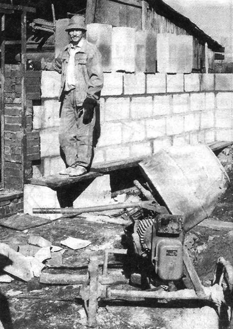
We first lived in an apartment in a three-story building, and then decided to move to a house of the estate type. But it required serious repairs, and the outbuildings were subject to complete replacement. Significant concrete work lay ahead. Memories of student construction brigades involuntarily surfaced, where we had to mix mortar in significant volumes using only a shovel. And so, to make it easier, I decided to make a concrete mixer.
Of course, it would have been easier to buy one (fortunately, the market now offers a wide selection), but at such a moment money (which, as we know, is never in excess) is much more needed for purchasing materials.
After rummaging through sheds, garages, and workshops at my place and friends’ places, I found suitable components and materials. In accordance with them, a general design scheme matured in my head, and the dimensions of the parts were determined as the work progressed.
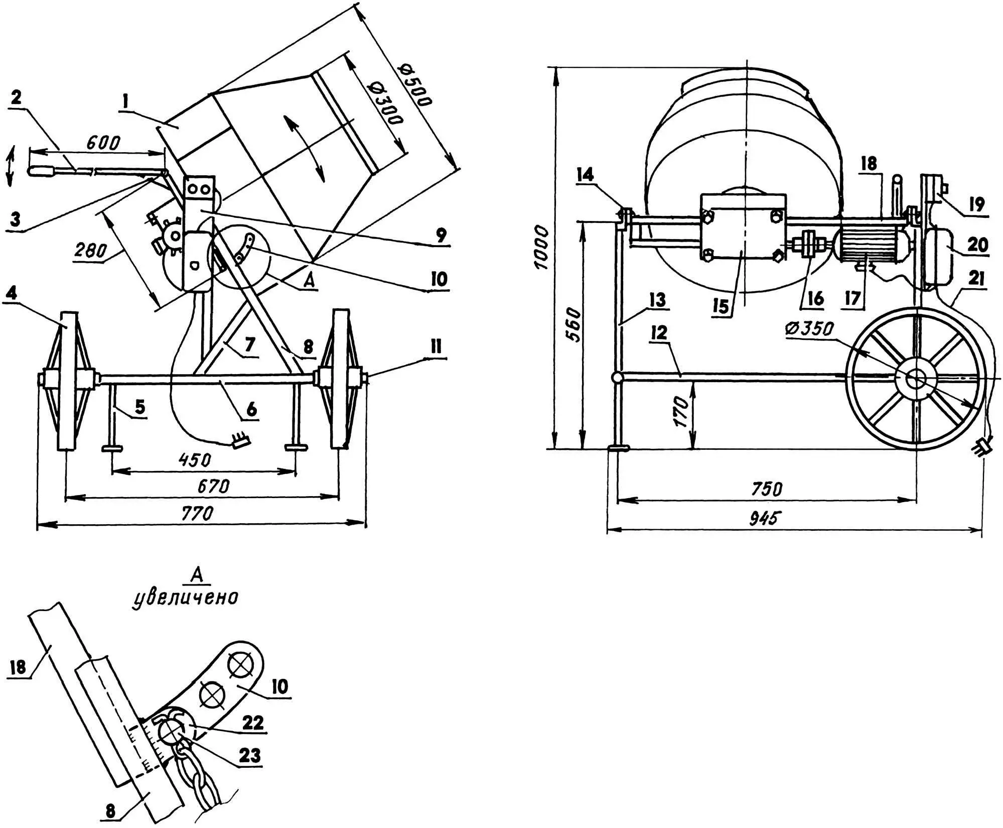
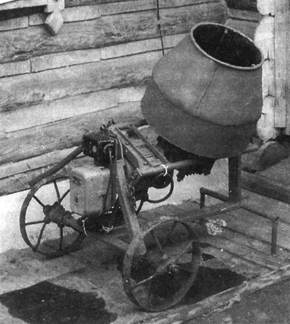
1 — mixer; 2 — handle-lever (1/2″ pipe); 3 — handle gusset (St3, sheet s3); 4 — wheel (from agricultural machinery); 5 — leg with base plate (1/2″ pipe and sheet s3, 2 pcs.); 6 — transverse frame beam (60×20 pipe); 7 — inclined post brace (1/2″ pipe); 8 — inclined post (60×20 pipe); 9 — panel (St3, sheet s3); 10 — mixer tilt adjustment sector with chain pin (St3, sheet s3); 11 — wheel axle (steel 45, round 16, 2 pcs.); 12 — longitudinal frame beam (60×20 pipe); 13 — vertical post (60×20 pipe); 14 — swivel subframe hinge lug (St3, sheet s5, 2 pcs.); 15 — worm gear reducer (i = 17); 16 — rubber coupling connecting motor and reducer shafts; 17 — electric motor (N = 1 kW, n = 950 rpm, 3-phase 380 V); 18 — subframe (side members — 3/4″ pipe, cross members — 35×35 angle, 4 pcs.); 19 — starter; 20 — capacitor box; 21 — power cable; 22 — lug (St3, sheet s3) for fixing mixer tilt (mixer tilt angle position, compared to the main view on detail A, is changed); 23 — pin with chain
I started making the concrete mixer with the mixer drum. First, I cut out the blanks: from 5 mm thick steel sheet — the bottom, from 2 mm sheet — a solid cylindrical belt shell and several “petal” sectors for the conical part (though the shell can also be made composite). Next, I gave the blanks the required radii and bends using a hammer and vise. Then I began assembling them. I tacked the belt to the bottom, and the petals to the belt (I also connected the latter to each other). I rimmed the formed neck with a 10 mm reinforcement ring and flanged the edges around it. After that, I carefully welded all seams with electric arc welding. Inside the mixer, I welded three more mixers for forced mixing of the mixture. I made them from 16 mm reinforcement bars.
The mixer rotation drive consists of a three-phase electric motor (powered from a 380 V network) with a power of 1 kW and a rotation speed of 950 revolutions per minute, and a worm gear reducer. Although the reducer is of unknown origin, it fit perfectly in its parameters: having a gear ratio of 17, it provides optimal mixer rotation — just under 60 revolutions per minute.
Both mechanisms are rigidly and coaxially mounted on a tubular subframe, and are connected to each other by means of a rubber coupling.
The subframe is hingedly attached (with the ability to rotate) to the main frame through 2 lugs with M10x40 mm bolts. The frame, although spatial, is very simple: its T-shaped base and posts (vertical and inclined) are welded from a rectangular 60×20 mm section pipe. The inclined post is additionally reinforced with a brace, and a panel is welded to it, to which the capacitor box and starter are attached.
The frame has four supports: two wheels (thanks to which the concrete mixer is mobile) and two legs. The wheels are from some agricultural machinery, without tires. The legs with a crossbar between them are made from half-inch water pipe. I welded flat base plates to the bottom of the legs to increase their support area.
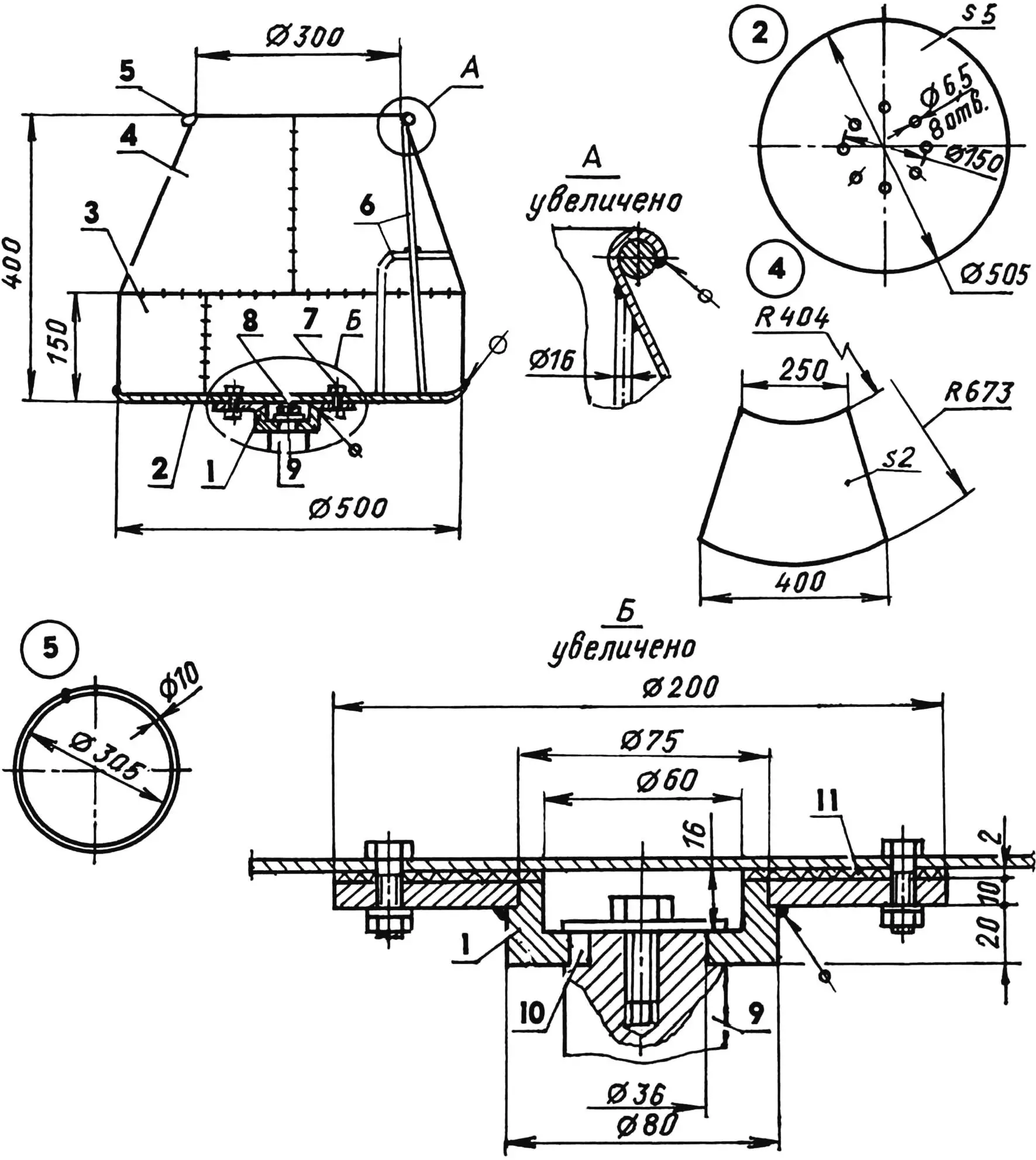
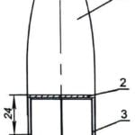
1 — flange-hub (St3); 2 — bottom (St3, sheet s5); 3 — cylindrical belt shell (St3, sheet s2, strip 150×2, L1580); 4 — conical part sector (St3, sheet s2, 4 pcs.); 5 — neck rim (St3, Ø10 reinforcement); 6 — mixture mixer (Ø16 reinforcement bar, 3 pcs.); 7 — M6 bolt, 8 pcs.; 8 — M6 screw; 9 — reducer output shaft; 10 — shaft key (St3); 11 — gasket (rubber, sheet s2)
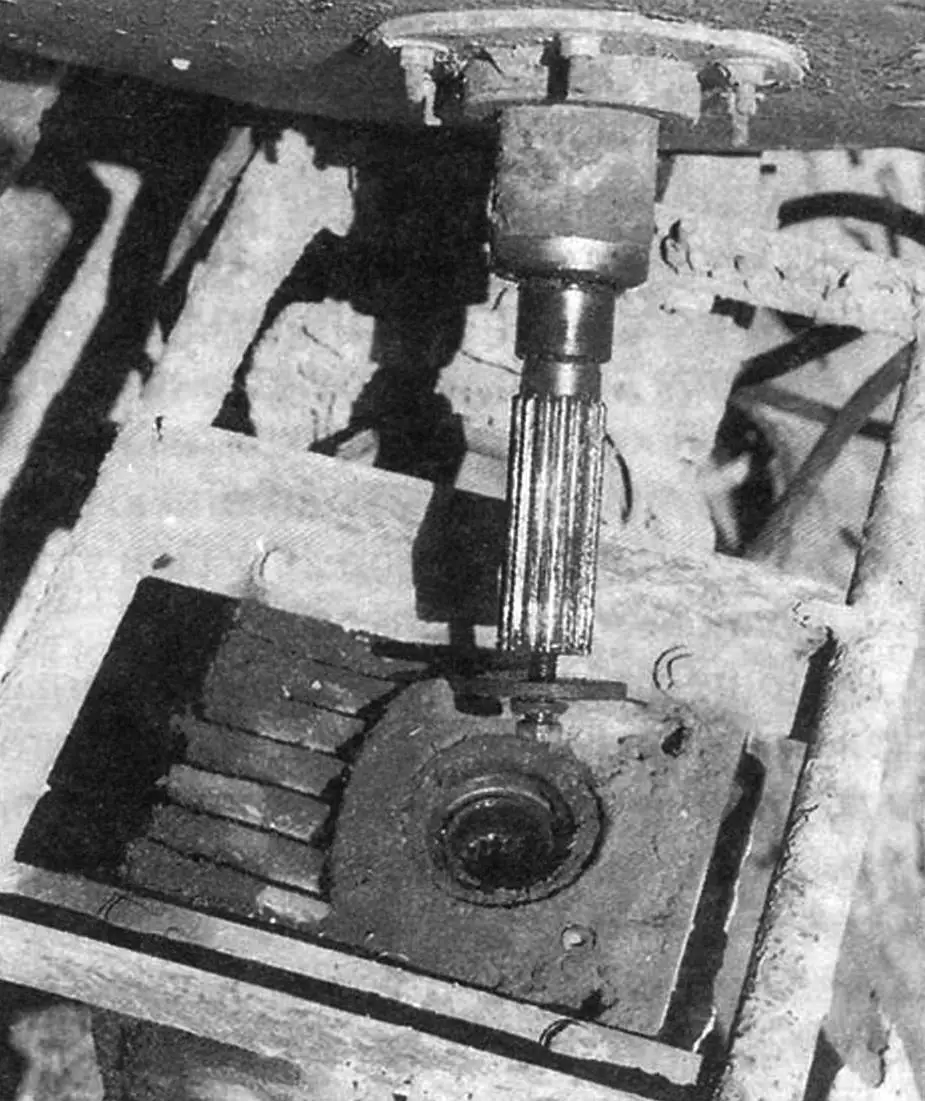
The mixer is mounted on a key on the reducer’s output splined shaft through a bottom flange with hub and secured with an M10 screw with washer, screwed into the corresponding threaded axial hole in the shaft end. For thorough cleaning (when even knocking off stuck mixture from the walls is required), the mixer is removed together with the reducer shaft (see photo).
In the empty state, the mixer position is balanced by the masses of the electric motor and reducer. But for work, the mixer is set at various fixed angles. For this, a lug with an 11 mm diameter hole is welded to the inclined post of the main frame, and a wide arc-shaped plate is welded to the subframe. A pointed pin is inserted into the lug hole, and holes corresponding to mixer tilt angles to the vertical of 40, 60, and 90 degrees are drilled in the plate as needed. These tilt angles most optimally correspond to the operations performed: mixing concrete mixture, preparing mortar, and washing the mixer, respectively. The pin, so it doesn’t get lost, is attached to the frame on a chain. The mixer tilt is performed by a handle-lever made from half-inch water pipe and welded to the subframe. The connection is reinforced with a gusset, and the handle is slightly bent to ensure convenient control at a suitable height. For unloading, the mixer is tilted until it stops against the longitudinal frame beam. Sometimes it’s more convenient to load components by raising the mixer to the maximum (at an angle of about 20°). In this case, the handle rests on the wheel.
Generally speaking, the concrete mixer is designed for a right-handed person of average height. If the owner-operator is left-handed, the design should be made in a mirror-image version, and if they are tall, the frame post height should be increased by about 10 centimeters.
At maximum mixer lift, the handle lies on the wheel, and at maximum lowering — the mixer body rests against the longitudinal frame beam. In the latter position, if necessary, “impact” cleaning of the mixer is also performed.
The electrical circuit is standard — such have been given more than once in “Modelist-Konstruktor” publications, so I won’t dwell on it for readers.
After a test run, I coated the frame, subframe, and mixer with primer, and lubricated the rubbing parts of the reducer, wheels, and hinges.
To enable moving the concrete mixer around the perimeter of the construction site, I made a 15-meter extension cord from flexible but strong cable.
I’ll add that the small size of the equipment often provides much greater capabilities: this is both ease of movement and maintenance, and improved mixing quality, as well as convenience of storage (not much space is required).
When preparing concrete mixture (or mortar — with an additional dose of sand instead of crushed stone), I follow the following sequence and loading ratio of components in liters (or dm3):
— turning on mixer rotation; — pouring water (6 — 8); — adding cement (4 — 6); — loading sand (10 — 15); — loading crushed stone (20 — 30).
The components are mixed for 3 — 5 minutes. During this time, I fill buckets for the next batch.
In one working day, I poured 10 m of foundation trench 1 m deep and 0.25 m wide, though I also threw rubble stone into it. I placed the concrete mixer directly over the trench at an angle, the wheels remained on one side of the trench, and one leg — on the other side (the second leg hung over the trench). In this case, the concrete fell exactly into the trench, and as it filled in that place, slightly turning the unit, I rolled it further.
Over the five years of the concrete mixer’s existence, with its help were built: a brick house with a massive concrete foundation measuring 10×9 meters; a garage with workshop made of aerated concrete blocks on a strip foundation measuring 12×5 meters; concrete cellar, cesspool, as well as crawl space and foundation for a sauna. For all this, more than 10 dump truck loads of crushed stone, sand, and slag were mixed.
In conclusion, serious advice to DIYers: before starting to build a house, and this is at least ten years of hard work, you should assess your strength and health in advance. After all, the concrete mixer only opens its mouth and chews, but the owner-builder feeds it with a shovel and bucket.
Technical specifications of the concrete mixer
Overall dimensions (length x width x height), mm … 945x770x1000
Motor:
supply voltage, V … 380
power, kW … 1
rotation speed/rpm … 950
Reducer gear ratio … 17
Mixer volume, l … 50
Mixer rotation speed, rpm … 56
Mixture output per batch, l
mortar … 20
concrete … 30
Productivity, m3/hour … 0.5
Weight, kg … 60
A. MATVEYCHUK
Recommend to read
 FLYING THE “FUNNEL”
In one of the reports of competitions rocketmodeler I noted an unusual model sports class Ѕ6А famous athlete Nikolay Sergeeva from Belgorod. How many know it, and you know we have more...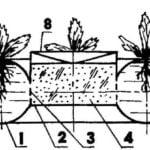 THE PATCH OF THE TIRES…
I read in the journal "modelist-Konstruktor" No. 6, 1993 article "Vitamins grow on the balcony." From her I learned about the use of pyramids of old tires as a vertical garden. Intrigued...
