Plowing can be done in different ways. Basically, the choice of plowing method depends on the size of the land plot and the availability of mechanization means to its owner.
However, on small household plots today, various types of tillers and winches are most applicable. The former are convenient because they are productive, economical, and maneuverable. The latter take the lead where not even a mini-tractor can turn around — even a tiller, that is, on difficult terrain. But even in this case, the homeowner again faces a choice of which winch to focus on — motorized or electrified.
Nevertheless, there is a third way — equipping the farmer with some universal means that has the advantages of both a mini-tractor and a winch.
This path was chosen by Viktor Dmitrievich Berezhnoy, an amateur designer from the city of Valday in the Novgorod region. On his dacha plot, he plows the land using a mini-winch of his own making.
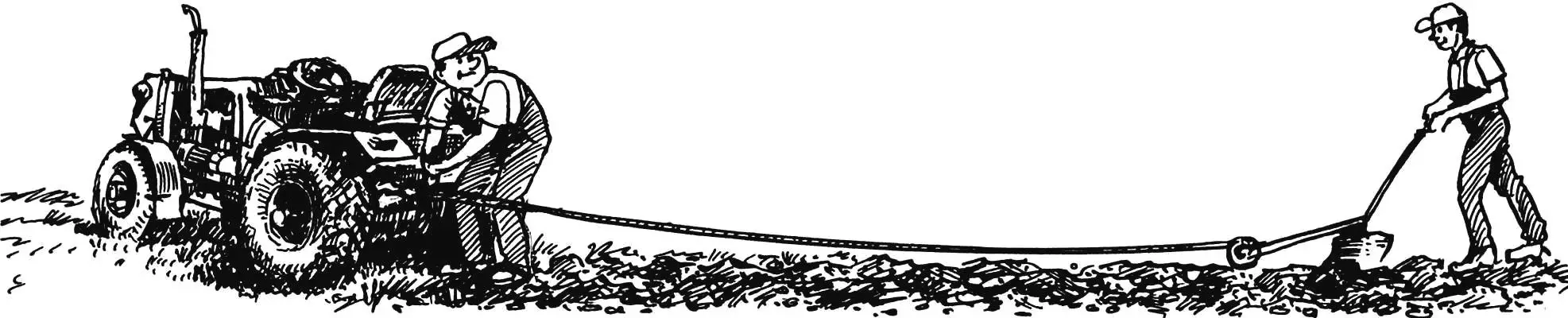
Like all plowing winches, the Valday one is also operated by two operators: one controls its drive from a homemade mini-tractor-tug, the second — the plow in the field.
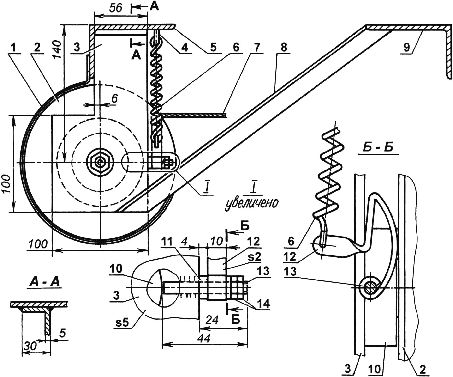
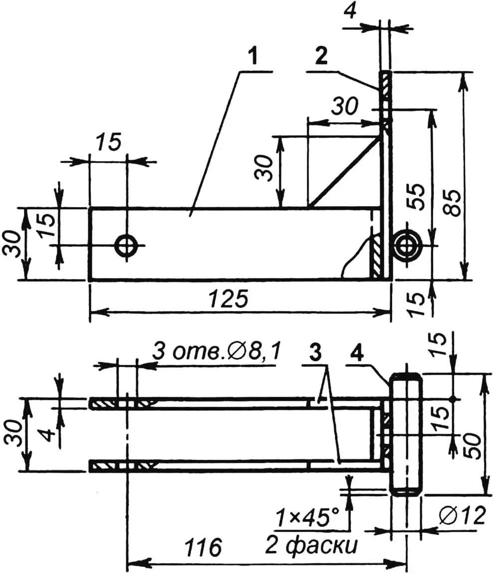
1 — protective cover (steel, sheet s1); 2 — cable drum; 3 — frame mounting bracket (steel, sheet s5, 2 pcs.); 4 — spring mounting hook; 5,9 — engine mounting shelves to tug frame; 6 — brake device spring; 7 — working cable; 8 — strut (angle 20x20x3, 2 pcs.); 10 — bearing housing 204; 11 — spacer washer; 12 — brake paw (steel, sheet s2); 13 — brake paw axis (stud M6); 14 — M6 nuts with Grover washer
The winch is driven by the tractor engine using a power take-off mechanism (PTO) installed on the gearbox (on the tug it is from a GAZ-51 car). This mechanism, which once extended a large antenna on a mobile radio station, has a control lever with three positions: “forward”, “stop” and “reverse”. The first is not used, since at “stop” and with the winch turned off, the cable can be easily unwound manually. This is done by the second operator, rolling the plow on a wheel built into it to the beginning of a new furrow. Having taken the starting position there, he signals the first operator. The latter turns on the winch and moves the power take-off mechanism lever to the “reverse” position. The drum begins to rotate, winding the cable, and the plow, controlled by the second operator, bites into the ground.
After passing the next furrow, the entire cycle of operator actions is repeated until the plot is finished plowing.
Now specifically about where the mini-winch is located on the tug and how it is arranged.
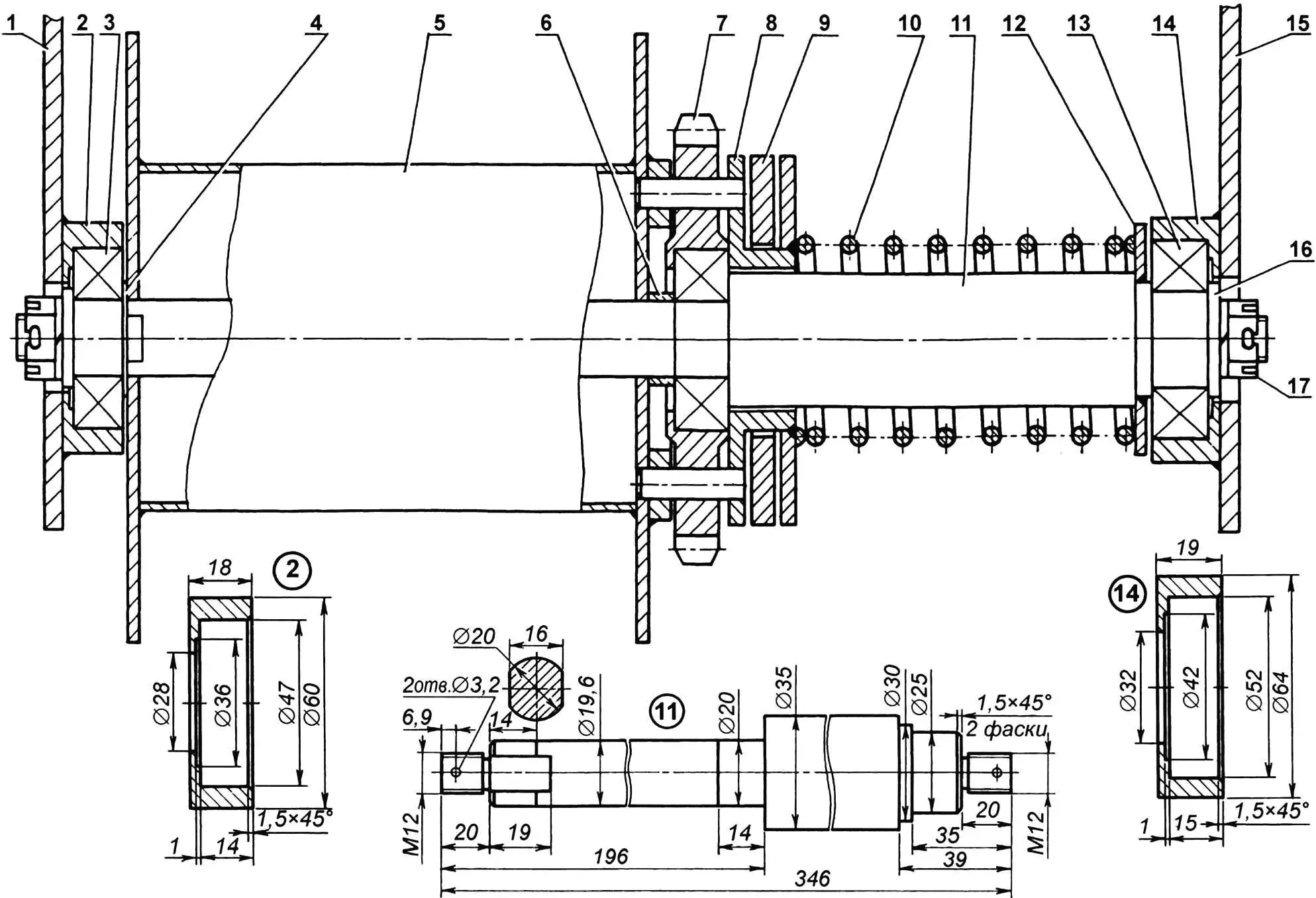
1,15 — frame mounting brackets; 2,14 — bearing housings; 3 — bearing (№204, 2 pcs.); 4 — spacer washer (s1); 5 — cable drum; 6 — spacer sleeve (steel, pipe 24×2, L7); 7 — sprocket (z = 18, t = 19.05); 8 — clutch; 9 — pressure ring: 10 — spring; 11 — shaft; 12 — support ring; 13 — bearing №205: 16 — clamping washer (s3, 2 pcs.); 17 — slotted nut M12 (2 pcs.)
The mini-tractor frame has two powerful transverse shelves made of angle iron measuring 90x56x6 mm, on which the engine is mounted. The winch mounting brackets are welded to the rear (in the direction of travel) shelf from below. In the transverse direction, the location for the winch was chosen so that its sprocket is in the same plane as the power take-off mechanism sprocket on the gearbox.
Since the forces on the cable during plowing are considerable, the brackets, even made of thick steel sheet, may not hold. To prevent this, they are supported by two struts made of 20x20x3 mm angle iron working in compression, welded to the front engine mounting shelf.
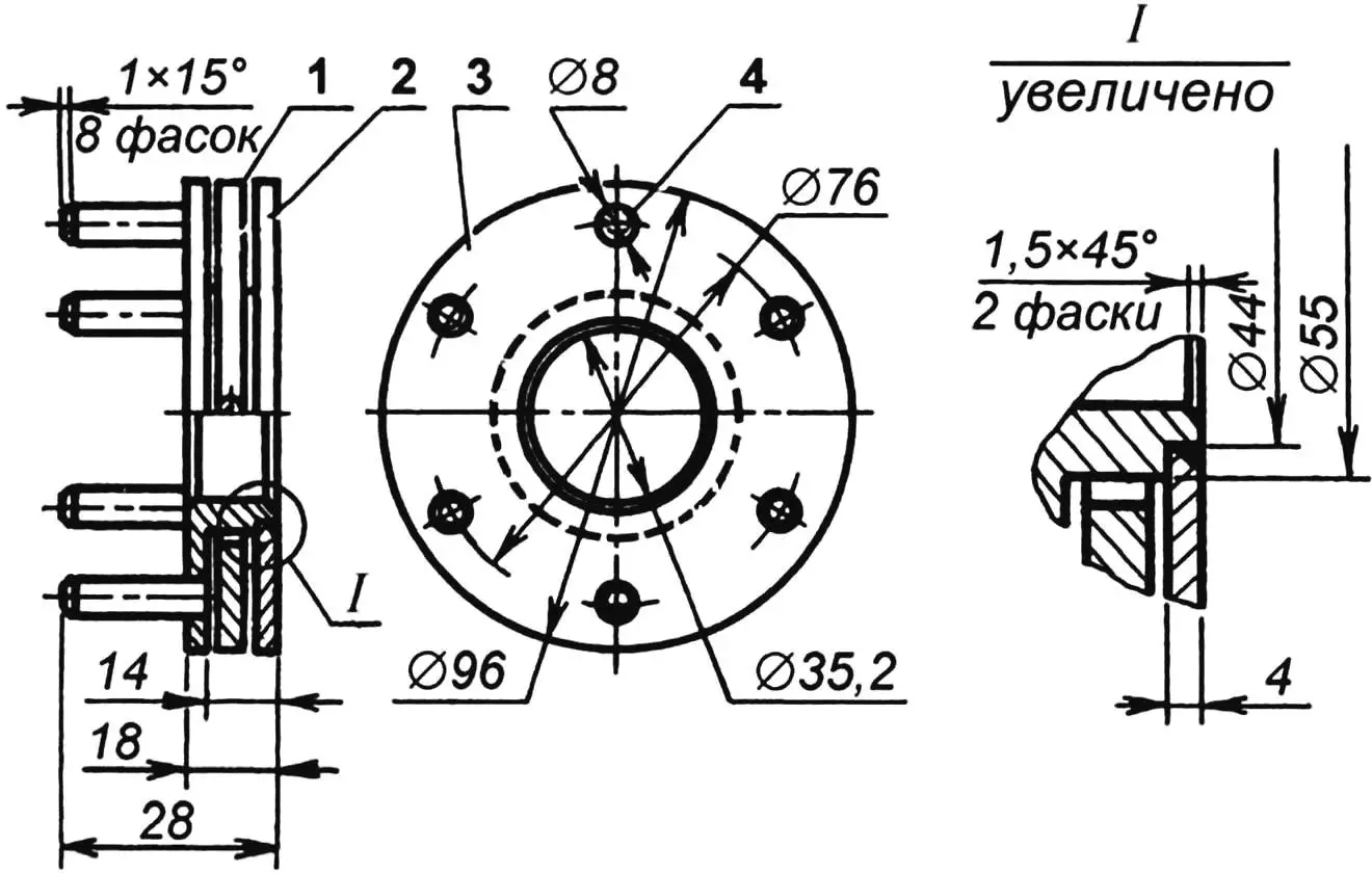
1 — pressure ring; 2 — wall washer (steel, sheet s4); 3 — housing; 4 — pin (steel, rod Ø8, 6 pcs.)
The winch itself consists of several fairly simple units and parts. At its core is a stepped shaft rotating in two bearings, on which are mounted a cable drum, a sprocket on its own bearing, a pin clutch and a compression spring.
In the working — engaged — position of the winch, the pins penetrate both the sprocket and the clutch ring on the left cheek of the drum through and through. Thus, the force from the engine through the gearbox, power take-off mechanism, chain and sprockets is transmitted to the drum, and it, rotating, winds the cable onto its barrel.
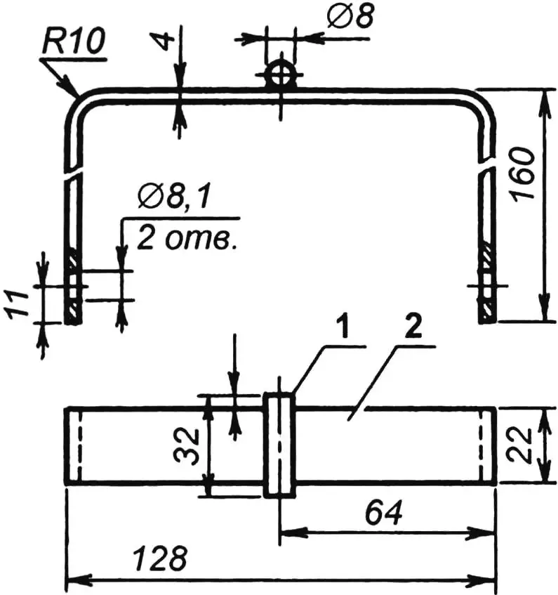
1 — large double arm; 2 — small arm; 3 — gussets; 4 — pivot axis (steel, rod Ø12);
material of parts 1,2,3 — steel, strip 30×4
When it is necessary to stop winding and release the cable for the plow to return to the beginning of the furrow, the first operator stops the winch by moving the PTO lever to the “stop” position, and then turns it off by moving the control mechanism handle backward. The elements of this mechanism are activated sequentially — rigid rod, rocker, guide and pressure ring. Under the pressure of the latter, the clutch, overcoming the resistance of the spring on the winch shaft, withdraws its pins from engagement with the clutch ring and sprocket. Now the drum is free.
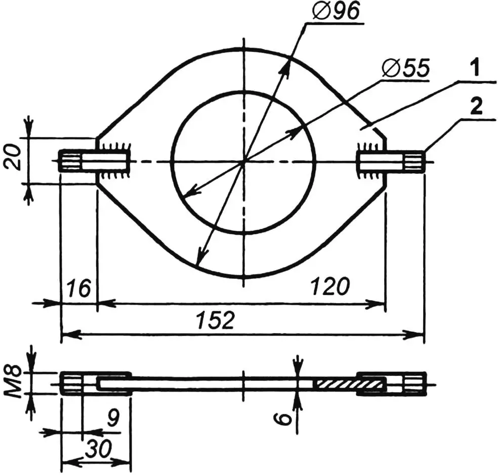
1 — ring (steel, sheet s6); 2 — axis (stud M8, 2 pcs.)
To ensure the cable winds evenly and does not tangle, the winch design includes a simple drum brake device. It consists of a bent steel paw and a tension spring. The paw is mounted on an axis-stud welded to the right winch mounting bracket on the bearing side, and the spring is put on the paw eye and on a threaded hook screwed into the rear engine mounting shelf.
Thus, the paw is constantly pressed against the right cheek of the cable drum. The fact that steel rubs against steel here can be neglected — this is not the case when a more complex mechanism is needed.
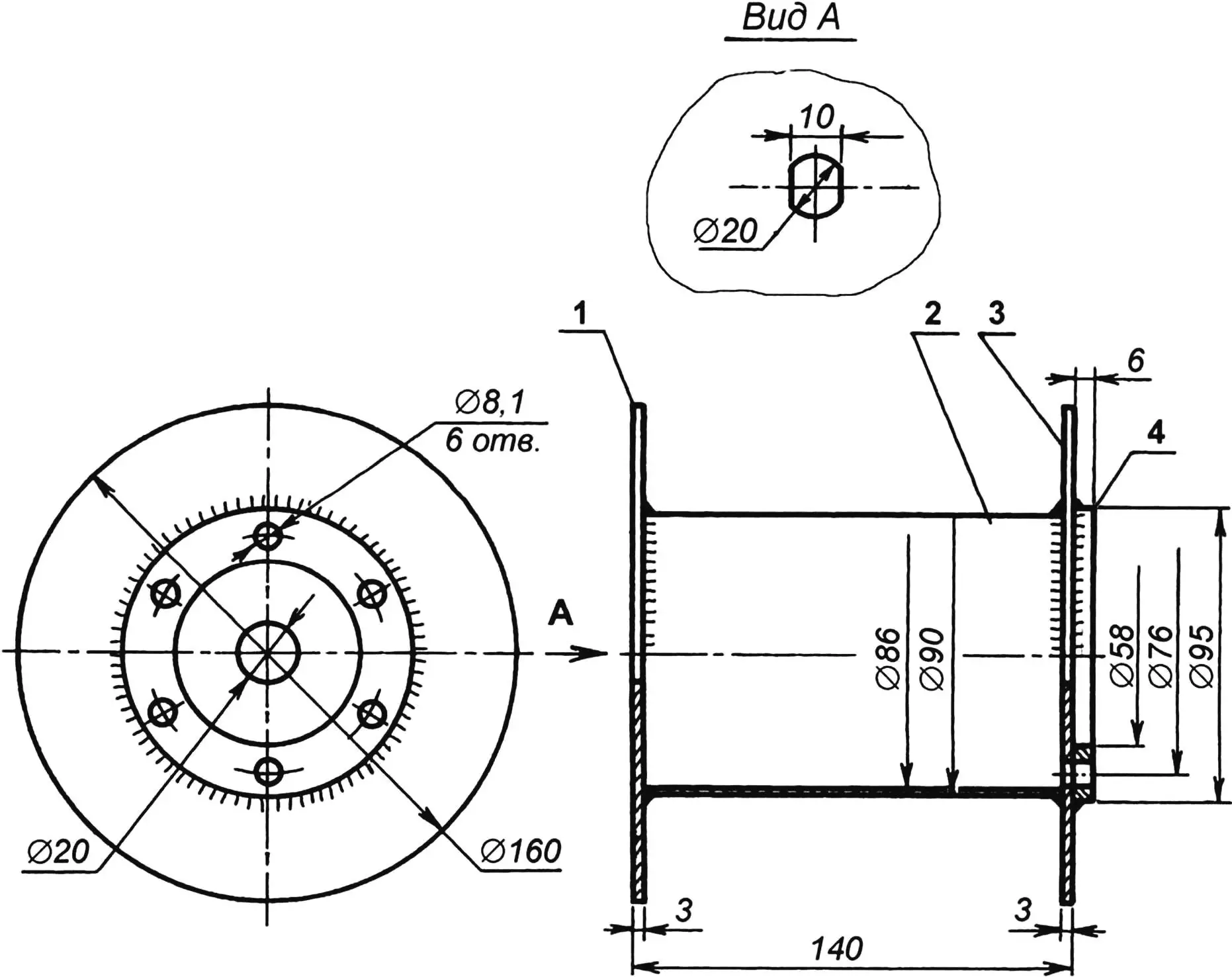
1,3 — cheeks (steel, sheet s3); 2 — barrel (steel, sheet s2); 4 — clutch ring
When winding the cable, the angular speed of drum rotation is low, and the resistance of the brake device is equally low. It becomes quite noticeable only when unwinding: the drum does not accelerate and does not outpace the cable.
The main technological method of assembling parts into units used in the manufacture of the winch is welding.
There were no difficulties when connecting brackets to bearing housings and the shaft to the spring support ring. It was much more difficult to weld the drum and clutch.
There are many options for assembling the drum. But the following can be recommended as the simplest.
1 — fork (steel, strip 22×4); 2 — pivot axis (steel, rod Ø8)
On the finished cheeks, circles corresponding to the barrel diameter must be drawn with a compass. Axial holes must be cut in the cheeks. Fix one cheek on the workbench and put three clamps on it at an angle of 120° relative to each other so that their upper jaws touch the drawn circle. Install the barrel on the cheek, press it with something and tack it around the circle with several weld points. Remove the clamps and finally weld the barrel with a continuous seam. Attach the second cheek and clutch ring in exactly the same way.
As for the clutch itself, it is easier to assemble. The main thing is not to forget after pressing the pins into the housing holes to put the pressure ring on the housing and only then weld the wall washer.
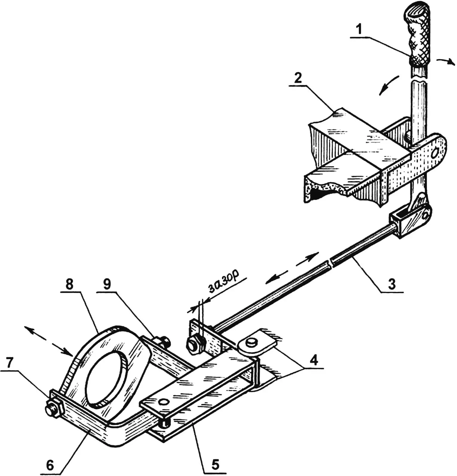
1 — control handle (forward movement turns the winch on, backward — turns it off); 2 — left rear corner of tug frame; 3 — rigid rod (steel, rod Ø8); 4 — eyes on tug frame; 5 — rocker;
6 — guide; 7,9 — hinge joints; 8 — clutch pressure ring
The sprocket with a bearing №204 pressed into it is from some agricultural unit. It only remained to drill six holes for the pins.
Naturally, the winch is used for one or two days during plowing and rides on the tug as ballast for most of the year. And on the road, anything can happen: suddenly the driver accidentally touches the lever or the power take-off mechanism spontaneously engages from shaking. So, to prevent accidental winch activation (and, as a result — cable breakage or, conversely, unwinding under the wheels of a moving tug), the control mechanism handle is fixed in the position where the winch is turned off, that is, when the spring is released and the clutch pins are withdrawn from engagement with the sprocket.
We can repeat and state that the winch design is quite simple. This simplicity is dictated by the functional and temporal limitations of its use. However, any design can be improved, if there is a desire. In this case, the field for modernization is very, very wide.
«Modelist-Konstruktor» № 10’2004, A. NIKOLAEV
Recommend to read
 “STAYERS” BLUE AQUADROME
We offer modelers design developed and successfully tested Czechoslovak athletes. The basis for its design was the model class F1E, with which the author is an engineer Ow. Valens was in... SUN PROTECTION
If the solar rays fall on the thermometer, mounted outside window frame, it heats up and shows... its temperature, not the ambient air. To avoid this, protect the thermometer shade...
