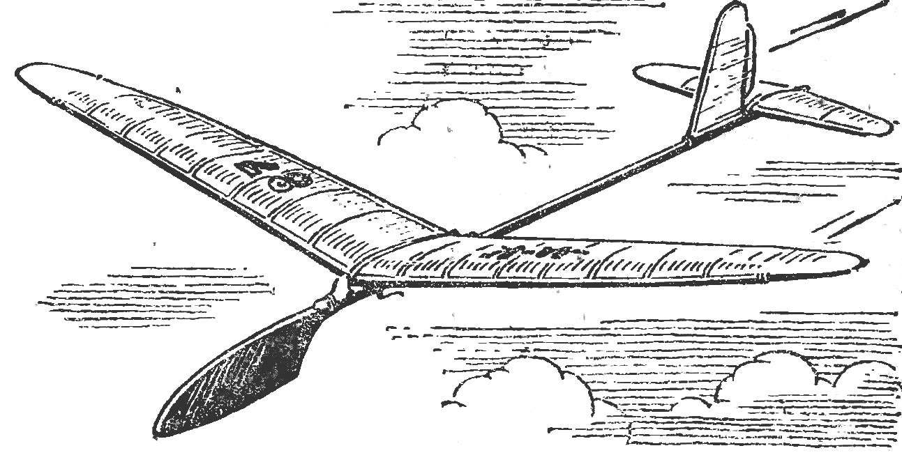
Elegant appearance, ease of fabrication, lack in construction materials in short supply, good flight characteristics are qualities that distinguish a schematic model of the airframe designed in the laboratory of aviation technology rut of Kazakhstan. Such models young Almaty residents repeatedly became winners of various competitions. Maximum results in all rounds is not uncommon when using the proposed “schematicity”. And flight characteristics of the glider was so high that it had to be equipped with a matchlock device forced landing. Without it, many models disappeared in terms.
Building a “little schematicity” begins with the wing. First of all billet bent edges (front edge only on V, the posterior for V and a narrowing of the end sections of the wing) with a specially made fixture. Before laying in a pine slats locations of future “fractures” moistened. To speed up drying, all heated on a hotplate.
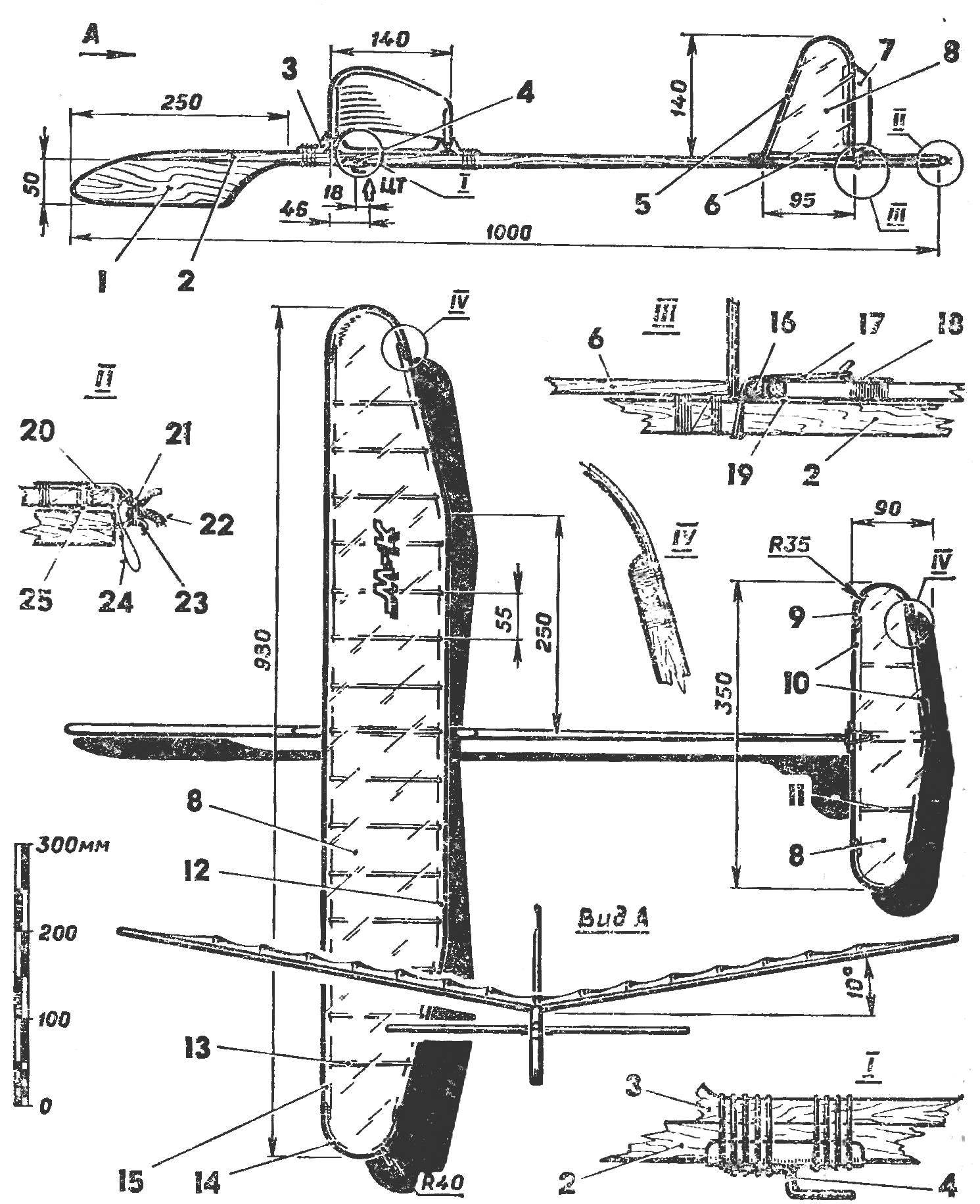
Rubber-band attachment on the fuselage and hook for attachment of a wick device. An important task facing the young athletes at these stages, to achieve the minimum weight of Kai stabilizer and fin.
Fig. 1. Schematic model of the airframe:
1 — the forward part (birch or pine 8 mm thick), 2 — the rake of the fuselage (pine 8X8 mm), 3 — pole (pine 8 mm thick), 4 — hook (OBC d 1.5 mm, solder on tin base), 5 — keel (aluminum wire 0 2.5 mm), 6 — rib keel (Sosna 3X4 mm), 7 — rudder (cardboard), 8 — a covering (Mylar film 0.02 mm), 9 — sakaizawa stabilizer (aluminum wire 2.5 mm d), 10 — edge of the stabilizer (pine SX X4 mm), 11 — rib stabilizer pine 2X3 mm), 12 — rear edge of the pine 4X7 mm), 13 — rib (pine 2×3,5 mm), 14 — ending (aluminum wire d 2.5 mm), 15 — timing edge pine (4X7 mm), 16, 19 — details of the lodgment of the stabilizer, 17 — rubber thread, 18 — hook stabilizer (OBC d 1 mm), 20, 23 — hooks hanging wick device (OVS d, 1 mm), 21, 22 — the elements of a wick device 24 thread limit deflection of the stabilizer, 25 — back lining.

 Elegant appearance, ease of fabrication, lack in construction materials in short supply, good flight characteristics are qualities that distinguish a schematic model of the airframe designed in the laboratory of aviation technology rut of Kazakhstan. Such models young Almaty residents repeatedly became winners of various competitions. Maximum results in all rounds is not uncommon when using the proposed “schematicity”. And flight characteristics of the glider was so high that it had to be equipped with a matchlock device forced landing. Without it, many models disappeared in terms.